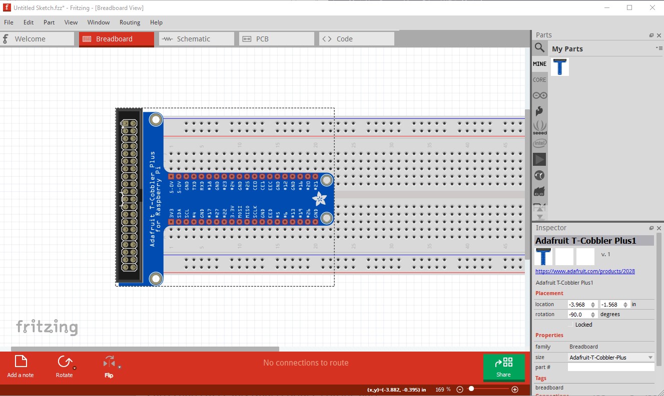
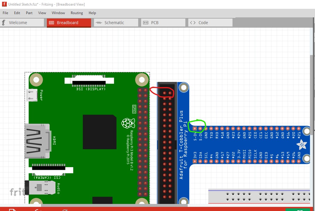
here I started the wire at the header end of the connection and it successfully connects to the breadboard, the left wire is how I started, drag the unconnected end to the breadboard and it will connect. Another couple of things to note, the Tcobbler is currently not connected to the breadboard (the connections are red indicating no connection) so you need to move it in x until the connections go green as in my screen shot. As well the tcobbler is not connected to the RPI, it is possible the tcobbler has the pins set to male in which case it won’t connect, I’ll check that when I look over the part, or you may need to turn off Align to grid (View->Align to grid) and then move the rpi til the GPIO connectors go green. I can’t make it do that even with align to grid off though so there may need to be parts changes. The GPIO on the tcobbler looks to be 0.05in offset from the pins that connect to the breadboard which will be part of the problem here as we see in this screen shot:
the RPI part is aligned correctly on the grid and thus won’t connect to the tcobbler GPIO. In any case I will poke further since I suspect the current behavior indicates a bug (moving forward and back should fix this absent a directive in the part.)
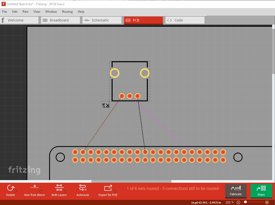
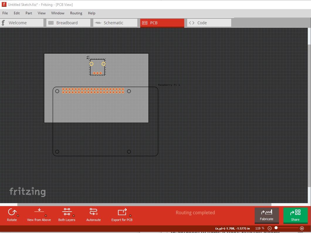
Unfortunately I don’t think it is fixable. What is happening is the bounding box of the part (the grey area when it is selected) is considered the part. In this case that includes the empty space to the edge of the GPIO connector and covers the entire breadboard. The breadboard is always the bottom most layer (and I expect something will break if that changes!), so in effect you can’t move the part lower than the breadboard and thus can’t connect wires to the breadboard in this particular case (because of the layout of the part.) In this case that means you can’t directly connect wires to the breadboard with the part in place. There is a workaround again, although it is somewhat ugly. Here I had to set the grid size (View->grid size) from the default 0.1in to 0.05in because it depends on which pin (which seems to change) Fritzing decides is on the grid. In this case it decided the GPIO pins were on the grid and the breadboard is offset 0.05in and won’t connect. The 0.05in grid size means I can move the tcobbler to connect to the breadboard. The work around is to connect the ground wire you want with the tcobbler moved out of the way like this:
now move the tcobbler back in to position and drag the end of the wire on to the breadboard and it will connect. This is ugly, but the only way I can see of doing it.
If you click on the ground bus here, you will see all the ground pins on the tcobbler light up yellow because they have connected to the ground bus. I’m working on a corrected part that will allow the gpio to connect to the RPIs, I’ll post it in a while.
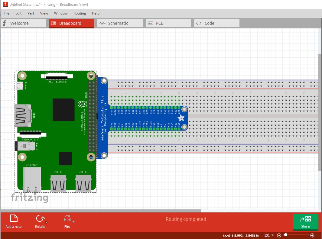
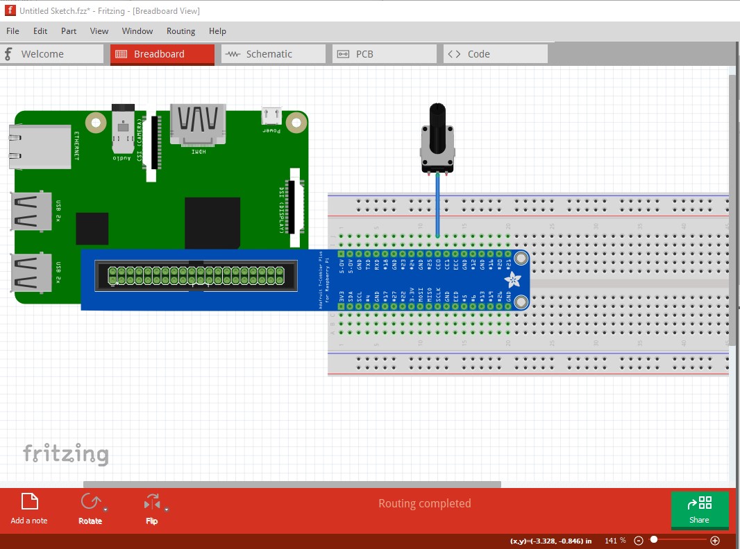
OK, after a bunch of thinking and experimenting and finding another bug (what fun ), I have something that mostly works. The trick is to change the part to a breadboard. With that done, the forward and back work in relation to the breadboard (but probably not other parts!) One issue is though I set the pins as male (and thus they should auto connect to the female breadboard pins) they don’t connect, so we need to cheat and use wires.
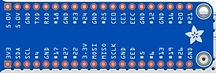
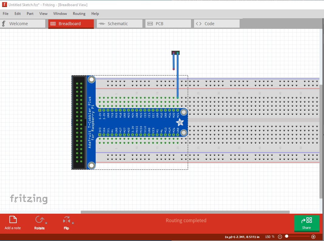
you may also notice the GPIO connector looks a little odd, I offset it 0.0 5in in X and Y so it aligns to the 0.1 grid the same as the breadboard pins. That means with the default 0.1 grid the RPI boards will mate with the GPIO connector (as we will see later) without having to adjust the grid size. I think not having to change the grid size is worth the small visual change. So, move the tcobbler up 3 positions in Y then connect wires from the tcobbler (you must start at the tcobbler!) to the breadboard position where the tcobbler started like this:
Now move the tcobbler back to its original position and the wires will disappear (but remain connected) vertically on the pins of the tcobbler. Note the pins of the breadboard on the tcobbler pins are green indicating they are connected.
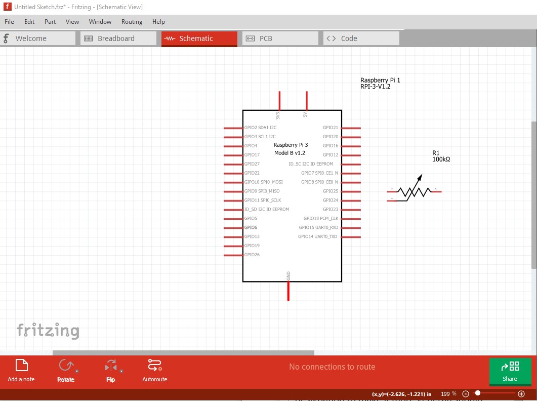
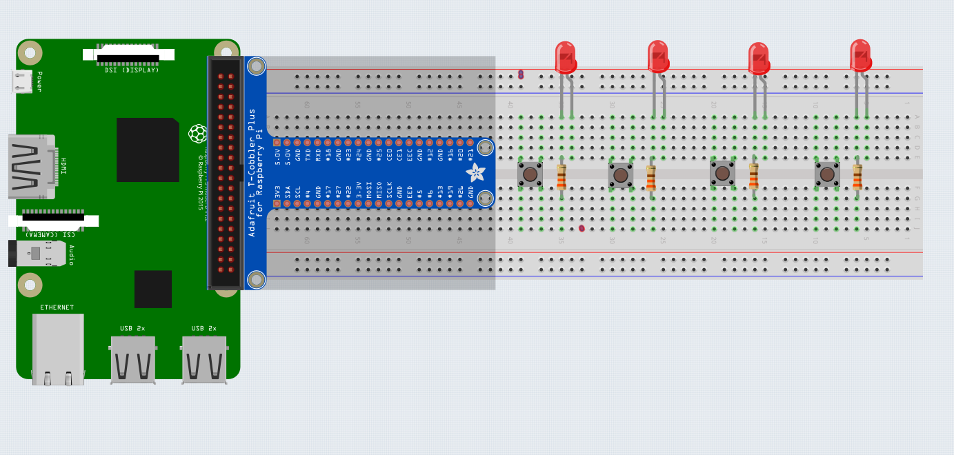
At this point, if you save this sketch to a .fzz file, that will serve as the base for using the tcobbler without having to connect the wires every time. Now drag in an RPI 3 part and we see it aligns with the tcobbler GPIO pins in X and Y.
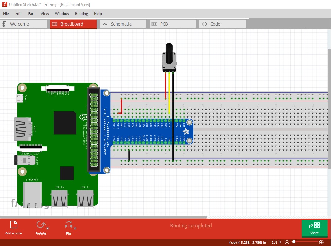
Here I have dragged in a pot from core parts with the intention of connecting the two ends to 5V and ground and the wiper to a random I/O pin on the tcobbler. To do that I selected the tcobbler, right clicked and clicked send to back. As the tcobbler is now also a breadboard it goes to the back as desired. Hovering over one of the green pins on the breadboard will bring up the pin label for that connector (best we can do unfortunately!)
Locking the breadboard and tcobbler parts in breadboard view can also help prevent accidental moves.
I was thinking about ways to solve this properly.
being able to create a custom shape for the part would handle things well, but getting away from a rectangular bounding box seems like a BIG project
something like the ability to split a single schematic part into multiple sub parts, each moveable, and with its own mounting box would work well
without those, creating this as 2 separate parts might work. One for the breadboard connections, the other for the raspberry header. Each with additional (almost invisible) connectors to connect to each other (male on one part, female on the other). Each of the extra connectors on a bus with one (or more for things like ground) of the main connectors. Place the breadboard part on the breadboard, then place the raspberry pi header on the breadboard piece. Like Peter’s adjustment, this would not quite lineup with a physical part, since need to keep all of the visible and invisible connectors on the 0.1 inch grid. To have enough room while preventing the breadboard part bounding box from getting wider, and preventing the header part from overlapping (hiding) any breadboard connectors, the header would need to be further from the breadboard part (or extend further out the other side). Need room for 40 connectors in the overlap region (minus however many can be dropped because a single bus only needs one joining connector). That is in addition to the 0.05 offset Peter used to get the header on the same grid as the breadboard.
That last case is another example where it would be very useful to be able to specify (during part creation) a specific (reference) connector that is to be aligned to the active grid. With that, the spacing would not need any adjustment. The 40(ish) joining connectors could be placed with smaller separation, keeping the relative positioning of the 2 pieces of the part correct. The part has (easy) room for 4 columns of 10 connectors on 0.05 inch spacing in the empty region between the breadboard and header parts, without extending either bounding box. If Fritzing could be told to not use any connectors in that block when considering how to align the parts to the grid.
Those schematic style sub parts would also be very useful in breadboard view for things like a cable harness. Basically 2 headers with virtual (invisible and bussed) wires between them. That would allow the breadboard view to stay much neater for some projects. Electrically equivalent to using a bunch of net labels in schematic view, but showing (if the breadboard graphics are done right) that it is a bundle of connections that start at one place, and end at another.
And just treat that (on schematic) like it was hooked to a raspberry pi? Actually, treat like a raspberry pi with a different form factor. Sure that should be simple. Should Just need to delete the unneeded graphics, connectors, and bus entries. May need to resequence what is left (definitions and all view svg files) to keep the validation checks happy.
So ‘simple’ but not trivial. I’ll let Peter comment on this later, since we was working with the previous version. It is almost 4AM our time.
Yes at least in breadboard. Because it is no longer a breadboard, it won’t invisibly connect in schematic or pcb, if all you need is breadboard then this will work. If you need schematic and/or pcb then as @microMerlin suggested truncating the extension where the RPI is and using the RPI3 schematic and pcb (removing the type designation to make it more general) should work.
I agree and I think the use case is too limited to make the effort worthwhile.
This one is worth pursuing I think. Pin alignment needs work for sure. I think from something that happened on the original part, that Fritzing picks different reference connectors on each load. One time the original part loaded with the RPI gpio connector on the .1 grid, so the breadboard portion wouldn’t connect to the breadboard (because it was 0.05in offset.) Most other times the breadboard portion was aligned with the breadboard and the GPIO connector had the 0.05 offset. At the very least a consistent reference pin would be useful and likely general enough to justify the needed developer time.
True, but again likely a lot of work and also possibly a performance issue. At about 10 or 12 complex schematic subparts rendering performance gets noticeably slower. I did a development board that had an embedded breadboard as the base part and more than 10 subparts of various kinds attached to it and locked some years ago and it was getting sluggish to render. I have some suspicion that bug fixing is going to eat all available developer time for a while though unless we get more bug fixes from the community which so far hasn’t happened (I’m afraid too many of the old technical folks that could do it have drifted away over the years.)


 ), I have something that mostly works. The trick is to change the part to a breadboard. With that done, the forward and back work in relation to the breadboard (but probably not other parts!) One issue is though I set the pins as male (and thus they should auto connect to the female breadboard pins) they don’t connect, so we need to cheat and use wires.