Programs/Applications that manipulate drawing elements (such as Difference, Subtraction, etc) do it via code that acts on drawn lines/objects using a combination of methods. Some do better at it, some, not so good. Hence, all the various menu items seen in those app’s.
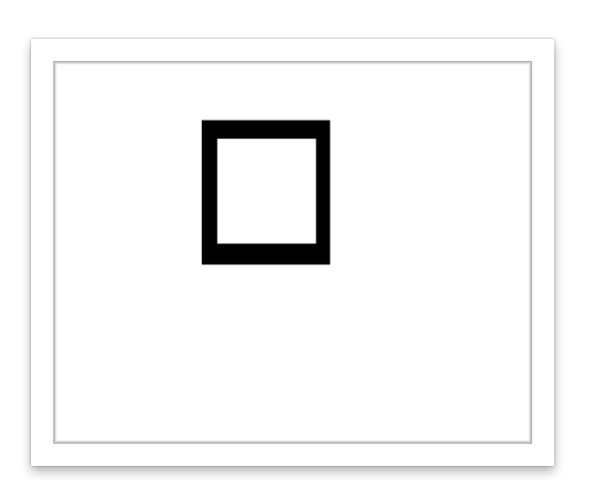
However, There are a few intrinsic manipulations that SVG can do: This Example will Subtract an Inner Box from an Outer Box. It is done by simply defining the corner points for the Outer Box in a Clockwise direction (Called ‘Winding’) and defining the Inner Box’s corner points CounterClockwise (called ‘Unwinding’). No Boolean, no fuss…
Example1 (image - I was not able to post the code):
The First “M” winds the outer box, the Second “M” unwinds (thus, an Intrinsic Difference).
Example2:
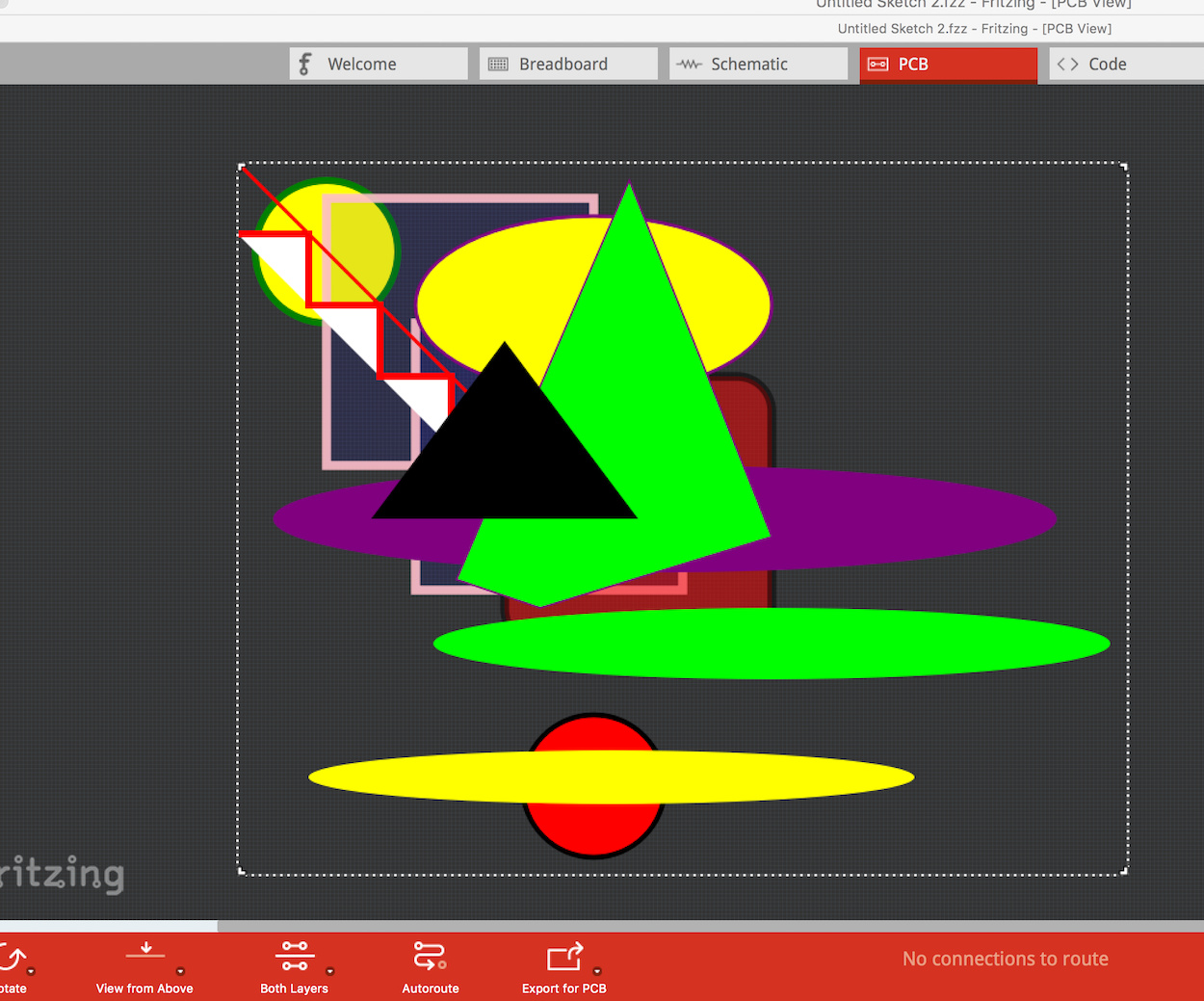
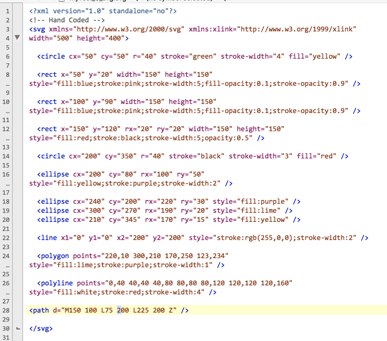
Examples of items learned from the Specification examples and the Tutorial - YES, Fritzing loads it without problems!
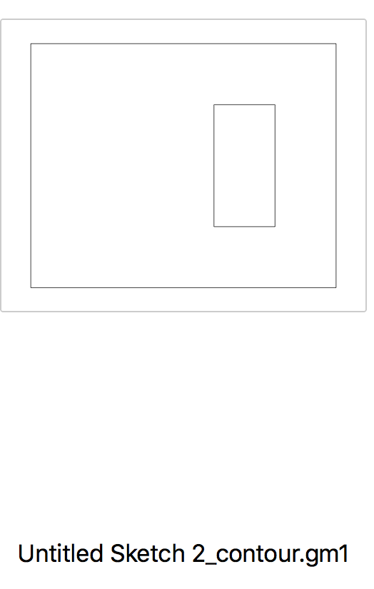
Example3: [EDIT] For the ‘Curious’ folks. Added an example of a PCB with a Cutout - all made using the principles shown in the Square with Cutout example.
It simply creates a Rectangular Clockwise Path and intrinsically subtracts a Counter-Clockwise Path for the cutout.
The cutout is closed via using a Moveto (you did learn what that is, I hope). It could use “Z” for closing the path but, that would not indicate (to Fritzing) there is a close path. Thus, it’s the correct way to close Cutouts.
No attempts to make a silkscreen, no layers are used and, no scaling adjustments. This is Pure SVG and Fritzing is Happy with it.
When loading, Fritz will indicate “No Cutouts” - Don’t worry - it’s only a ‘Message’ and does not cause problems.
Results shown in the Contour gerber…
I suspect the secret is the " uses a moveTo for closing it, instead of “Z” close path" which is a valuable addition to the knowledge base here. It seems to me that there are bugs in the path render part of the gerber code in Fritzing that are causing the odd results. As far as I can see the path xml for all examples is valid, i.e. it renders correctly both under Inkscape and in Fritzing in pcb view when Qt renders the xml, it only renders incorrectly after gerber processing indicating to me that the problem is in gerber processing not quite rendering all paths correctly. If we can figure out what it doesn’t like, we can (given the necessary knowledge of path creation) manually adjust the path xml to create successful cutouts til we can arrange to fix up the code. That may take a while to do, as someone will need to understand it, and be willing and capable of making the changes. As I said earlier I’d like to see that code change make the slot capability available in a part, which is probably an even bigger yet change, as that is where it will be most useful. When development ramps up again, hopefully someone more experienced than me will step up to do it as it is likely to take me a very long time to be successful at this given how much effort the two simple bug fixes I have already done have been. At the moment I’m poking at the parts factory code with the view to fixing up the scale of headers, making 2mm and 1.27mm headers work correctly (2mm currently makes pads that short together by default in pcb view) and hopefully fix the mess in breadboard with double row connectors (right now I think that should be fairly easy, we will see if it turns out that way ). For anyone who is a coder, they are accepting pull requests against the development code base on github again, as noted I have a couple of simple fixes accepted.
Regarding"Part’s": Had some success with exporting Etchable SVG but, no success exporting Gerber ‘Contour’ files.
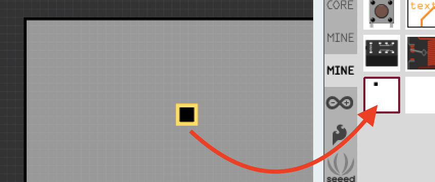
The only approach that was half-successful was when using an ID of ‘nonconn’ for the shape (a square for the test - see attached).
Exporting as ‘etchable svg’ produced the necessary files for etching. That’s good.
Of course, no Contour file is exported with SVG and, for my needs, anything less than a Contour file is not usable.
I’m convinced the Current Best approach is doing the cutouts on the PCB-board at the locations needed for a Part requiring cutouts.
Last year I messed with compiling Fritzing using QT and had an issue with lib2… (can’t remember exact issue at the moment). I decided I did not want to spend hours looking at code others created and I ended up deleting the raw fritzing code and moving on.
My version of QT only enables exporting locally for my Mac. So, it’s useless for real programming and multi-platform.
I may write a ‘Java based’ PCB(board)-Making app with a drag & drop ‘cutout’ capability. Thus, I envision: load a Part needing cutouts, drag&drop the cutouts at desired locations, save (i.e., Grab the currently loaded PCB, add the cutout and Save it). Sure, it’s band-aid approach but, would work.
However, as I’m able to accomplish everything I need to do via Hand-coding and/or Gravit, Boxy or Inkscape for Parts and PCB’s, I’ll most likely just watch the progress other are making. No doubt, I may play around more…
I agree, at present this is the only way to do this I think.
The new team had the same problem, they ended up having to static link the libgit2 library to make it work on the Mac. I assume the development repo on github will have the code to make that happen for anyone who wants to try.


 ). For anyone who is a coder, they are accepting pull requests against the development code base on github again, as noted I have a couple of simple fixes accepted.