SVG Export of wires with bendpoints

Hi there,

Today I was exporting a fritzing file which contains wires with bendpoints, aka segments, both curved and straight in the same wire, when I realized two things:

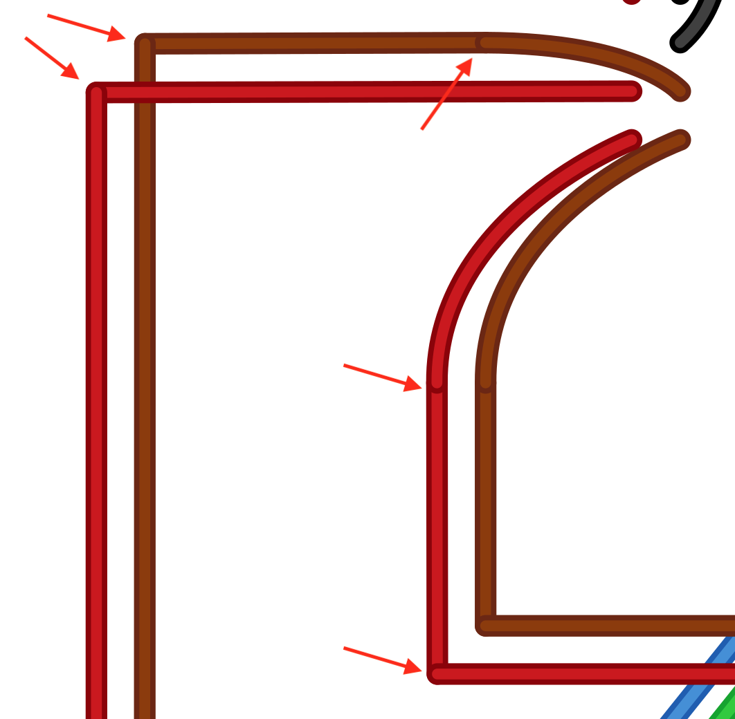
  1. The straight wire segments are exported as “line” SVG elements, while the curved segments are exported as “path” elements
  2. Every segment is separated, which gives a non-continuous wire (see image).

My goal is to create a Python tool (script) to “fix” that export so I can get continous wires combined in uniques paths. As far as I can tell now, that would involve two steps:

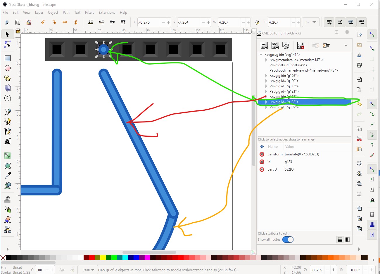
  1. locate all (SVG) line elements that form a wire
  2. join them in an unique path element (both internal color and external color).

Has anyone done/tried that before? I have searched the forum without success, but want to ask before reinventing the wheel… :sweat_smile:

Regards!

I`m not aware of anyone doing this. It looks at first glance to be fairly complex (@microMerlin is probably your best bet for path advise) as the there are three segments to the wire:

an end dot a line segment and a path all in different groups. This was generated from this svg (which is zipped and called .fzp to fool the forum, download the .fzp and unzip it to get the svg.)

test-Sketch_bb.fzp (1.4 KB)

Inkscape can probably (althoughI’m not good enough to do it) convert this to a single path. It is possible that you could parse the xml figure out the overlaps (to identify what is part of the wire) then convert that to a path. The fz file for the sketch will have the line Ids in (although whether in a usable form is another question, they are likely moduleIds in the database.)

Peter

So I kinda dug thru this a little, and here’s what I see…

A line is defined by 2 points, its start and end locations. Each point has a x & y value that is the location of that point. Pretty simple to understand.

A path is more complicated. A path is defined by the attribute:
d=“M 60.7607,64.7474 C 71.2371,65.7876 75.8233,46.775 75.8233,46.775”

Which tells me nothing. So I looked this up and found this:
https://www.w3.org/TR/SVG/paths.html
Basically, the d attribute is a series of commands and values that describe how the path should appear.

I assume, to combine a line and a path, you would need to figure out what the d attribute would be for the combined line & path. In vanepp’s file, when the light blue straight line and curved line are combined, the d = “M 75.812908,46.775002 54.296006,3.65241 m 6.4543,61.094992 c 10.476402,1.0402 15.062602,-17.9724 15.062602,-17.9724”

Looking at that page in the above link, it describes what the commands and values are.
“M 75.812908,46.775002 54.296006,3.65241” = absolute move to location (x,y)
“m 6.4543,61.094992” = relative move to location (x,y)
(see here )

So it is certainly something that can be done, but I’m not seeing an easy way to do it.
Anyway, that’s what I found on the subject
Randy

edit: by saying - not seeing an easy way to do it - I mean from a python script. It’s not too hard to do from Inkscape - ungroup lines and paths, convert line to path, combine this with the curved path, set fill paint to ‘no paint’, and done.

That is actually move absolute AND draw line to absolute point. There is an implied “L” after the M x,y.

MDN is a more usable reference. “d” attribute, path commands

The base case is quite simple. Since the lines and paths start and end at the same point, if you can sort the segments into the “connected” order then:

  • a line after a path (with absolute coordinates) is just “L x,y” added to the end of the path.
  • a line before a path needs to change the leading “M x,y” to “M x,y x,y” (or “M x,y L x,y”) where the second x,y is the original move coordinates.
  • for a path starting where a previous path ended, remove the leading “M x,y” from the second path, and append the rest to the first path

The tricky part is to get the order correct, since the adjacent segments could be running opposite directions. A line is easy to reverse, but not curved paths.

The brute force way to do it, is to turn all of the line segments into paths as “M x,y x,y”. Then if the path segments are all absolute, they can all be joined into a single path as “M x,y … M x,y … M x,y …”. The order does not mater. The rest of the attributes (stroke, stroke-width, …) should just carry over from the elements being combined. Paths that start with a relative move, and contain relative path commands need a little more. “m x,y” at the start of a path is the same point as “M x,y” (“m” is relative to 0,0, so is identical to “M” as first path command). The difference is the implied line after that is relative or absolute. So (not tested, but should work) change a leading “m x,y” to “M x,y m 0,0”.

Thanks everyone for the replies.

As both @just_randy and @microMerlin already explained, the idea is quite simple, just tedious-tricky to program: I’m no fan of xml parsers. That’s why I asked in the first place, just in case someone already did something similar.

I’ll post here my progress, for now I just fixed manually (with Inkscape’s support) the file I needed.

Regards