For many Fritzing parts, such as DIP IC or Mystery Part, there is a text item in the SVG file, e…g.:
<text id="label">74HC9999</text>
You can then modify the “chip label” property of the part in the user interface and the label will automatically update in the breadboard and schematic views.
However, if you create your own part, this doesn’t work, the text in the SVG file appears.
How does this mechanism work and what are the rules? I have been trying to read the source code in fritzing-app/src/items/dip.cpp, which seems to be calling the code of the Mystery Part to make this happen, but I have no clue if I can use this mechanism reliably for my own parts.
Your problem is that you are doing only half the required steps. As well as the svg files you also need to modify the properties field in the .fzp file.
you also need the property name=“chip label” and its default value (that can be modified by Inspector) to trip the special code that will substitute the value of the label field in the svgs.
There has to be another rule. I have the “chip label” property as you describe, but still am not seeing the label being replaced. What is probably a hint, is that the “chip label” property doesn’t result in an editable field, but in a drop down list in the part inspector. However, it is present in the fzp file as you describe.
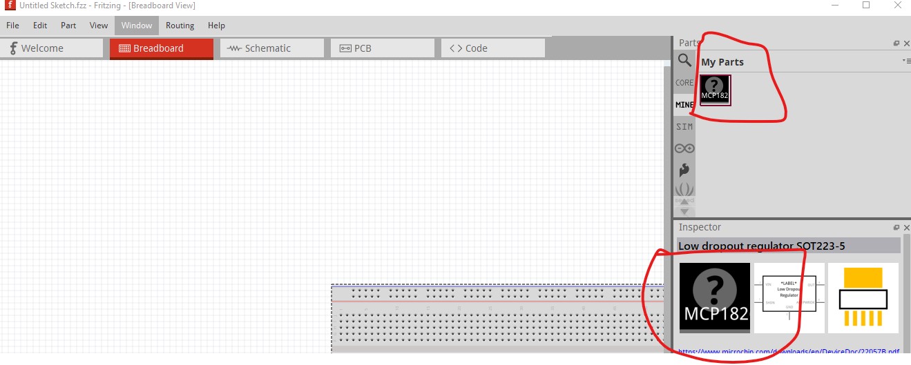
I’m attaching the part, perhaps you can quickly see the problem with your advanced part creation skills
It appears I misremember. I thought that I could change the chip label on the 74x125 part, but even back on 0.9.3.b (where the part was made) it in fact doesn’t work. It appears it will only switch between the chip labels in parts in the family, so to make this work you would need to make a new part with a different variant for each new part you want. Sorry for the misinformation! As well you may want to make this change to make the icon for the part match better:
file which is no longer needed as it will reuse the breadboard svg as the icon svg it will change to being the breadboard image which will be more sensible (although either will work fine!)
Indeed I still need to look at the icon and also the breadbroad graphic doesn’t look great yet. As the part is usable for a lot of LDO regulators, it would be nice to make it a “generic” part, but I don’t think this is really feasible. Copying it many times is likely not that productive. I’m using an MCP1826 in my currect project so I think I’ll make it an MCP1826-only part for now.
There has been discussion on how to achieve that, but nothing so far has come of it. At present separate parts in the same family (that can be swapped between by the swapping mechanism) is it. The swapping mechanism if probably some of the problem here as well it makes any such change more difficult I expect.
The mechanism to be able to change some of the properties is related to the sufix of the module ID of the part or the family. You could set the family of your part to: mistery part. That will trigger the code to set your part as a midget part. I’m not sure if this will work as you want, but you can try.
To set it as a dip part, see the family to: generic ic
It accepts the change in Inspector but doesn’t make the change in the svg (possibly be cause it isn’t really a Generic IC which I believe has a specific svg format and will be reformed by the parts factory code.) That would have problems anyway I expect because changing to one of the pull downs in Inspector will likely not let you return to this part as it isn’t part of the parts factory and the code will only recreate something the part factory knows how to create.