OK here is an improved part and what I did to it and why. This is all described in this tutorial if you haven’t seen it.
Starting on the breadboard svg, add construction lines and adjust placement and size of items to match the datasheet. Replace the mounting holes in the outline path with circles because they are easier to change than the path. Add construction lines to place the various components according to the measurements from the data sheet. Set connector0pin connectors will increase by 1 going up then start on the second row and do the same (because that is how the schematic extension wants to see them.)
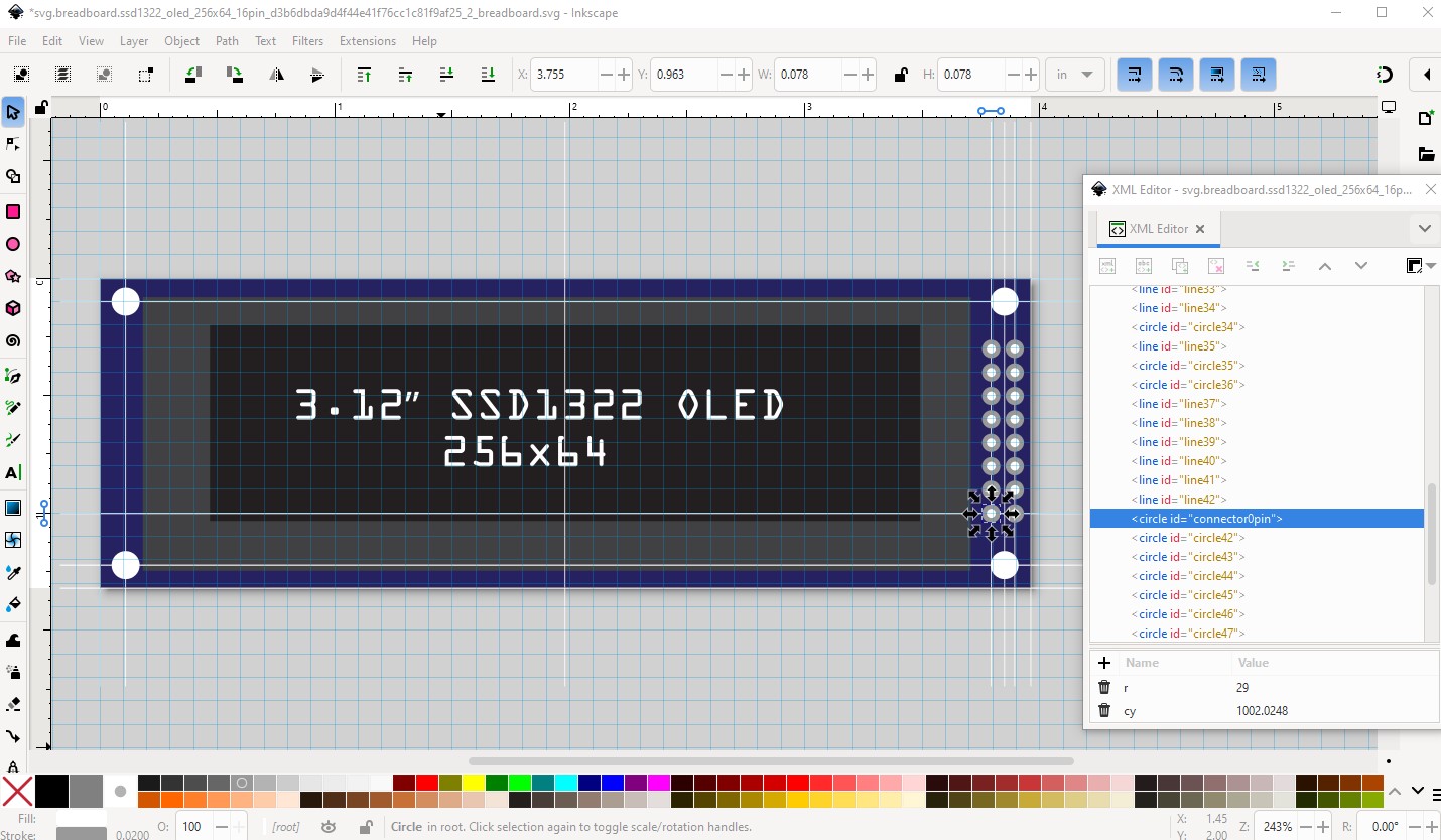
here is the breadboard svg with construction lines still in place for reference (right click on the image and click save file as to download it.)

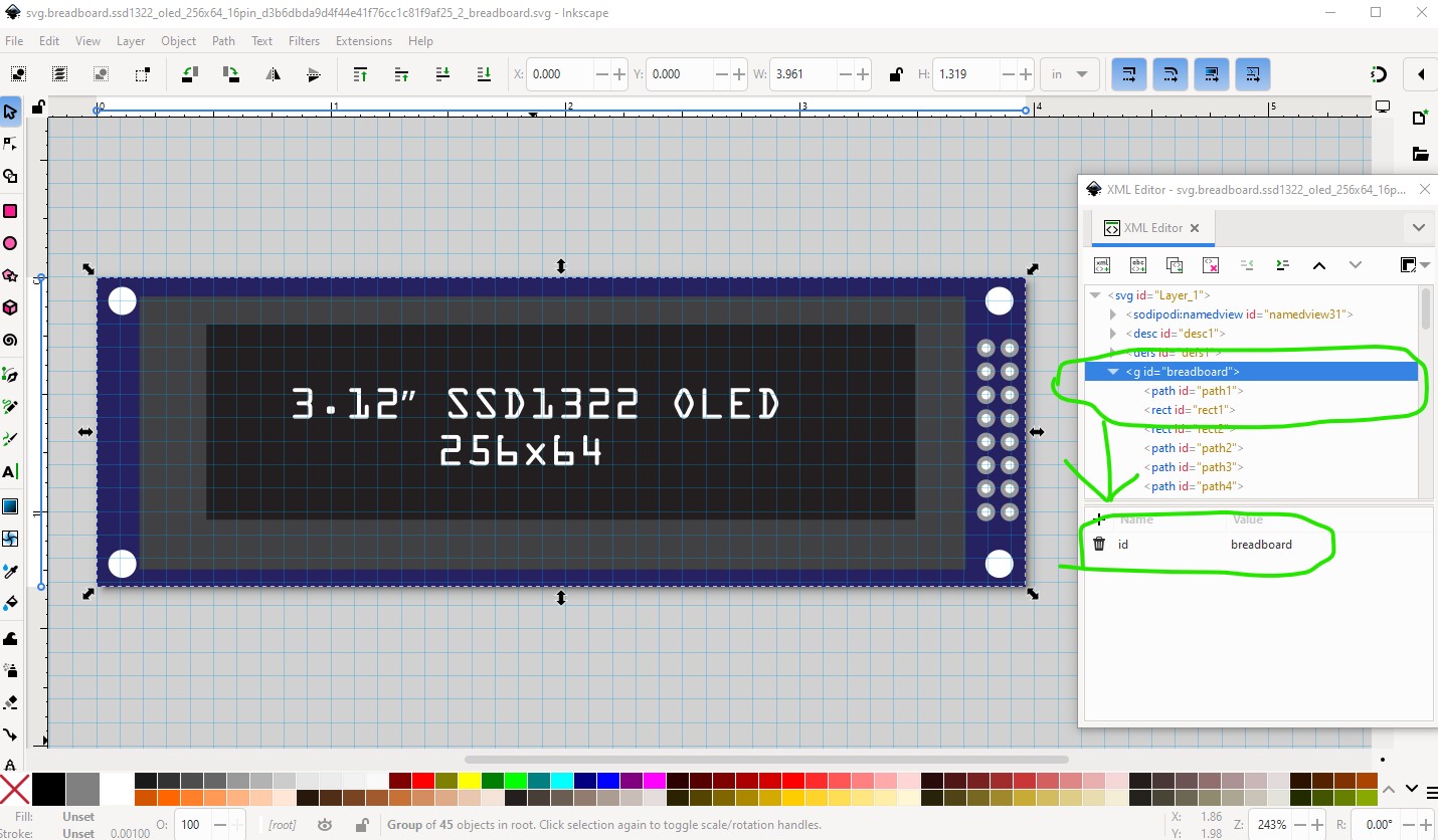
final breadboard svg with correct layerid set (missing in the original part!)
Missing layerids means the part will not export as an image.
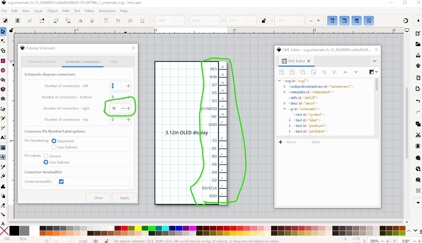
Schematic made with Randy’s Inkscape schematic extension which is the easiest way to make a correct schematic (although it requires some preplanning of connector layout.)
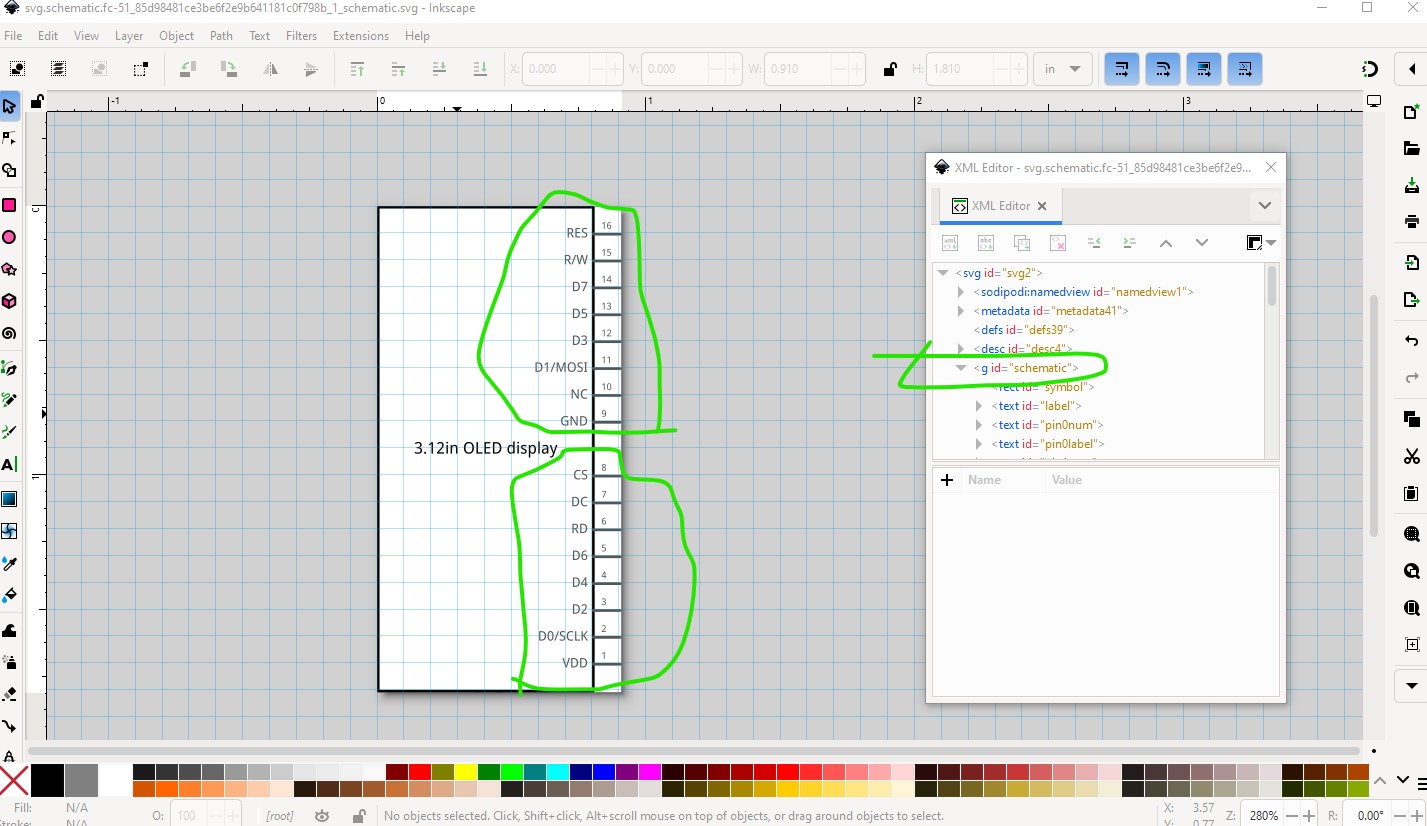
The connectors are on the left side (as they are in breadboard) and split in to two groups to represent the two rows of pins.
first config screen
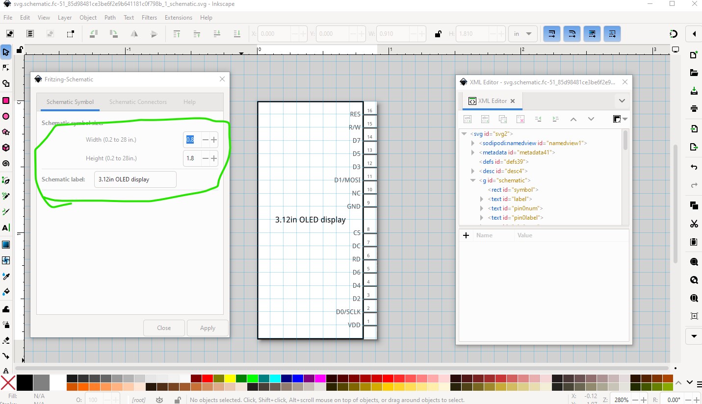
and the second config screen
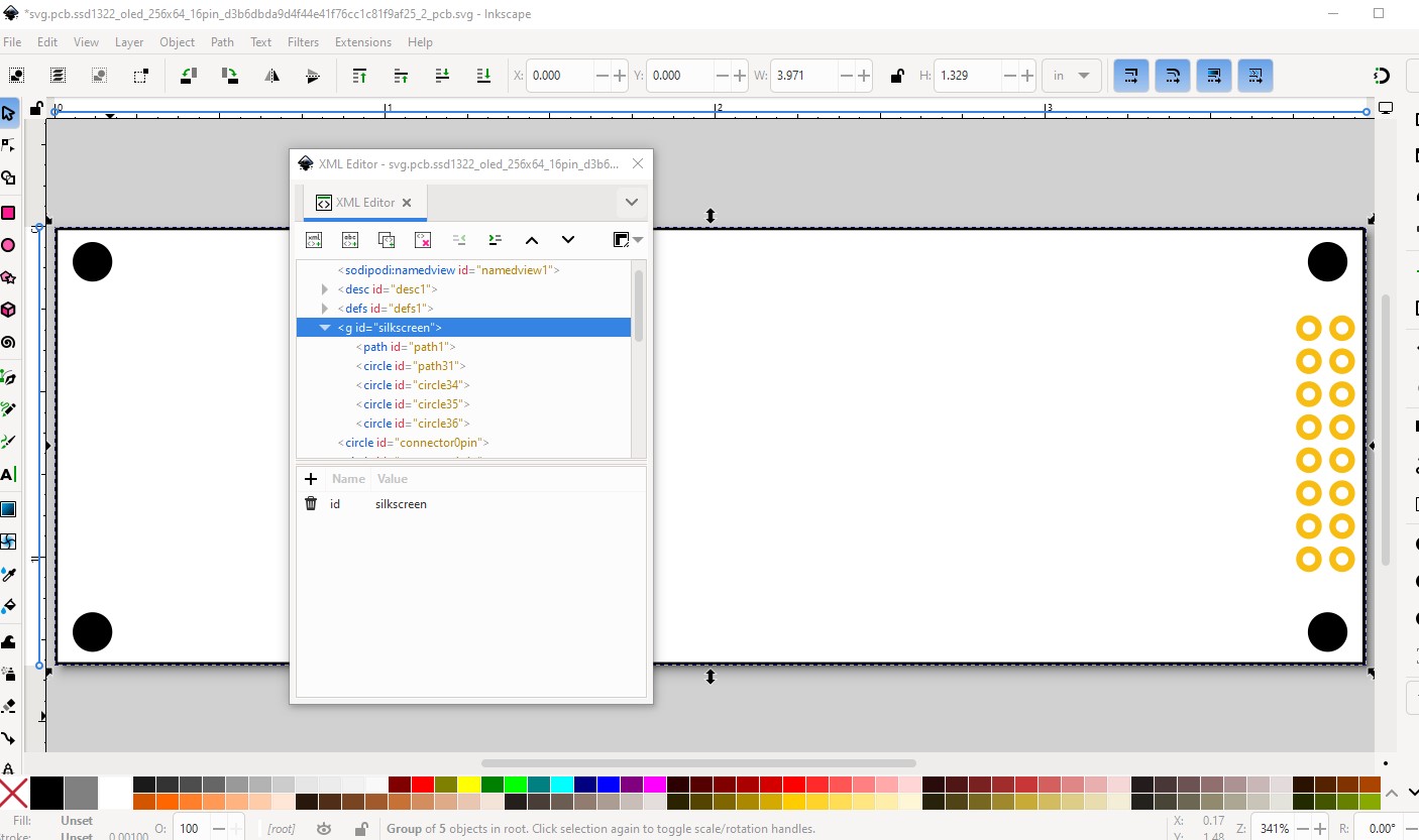
Now copy the breadboard svg to the pcb svg and edit it with Inkscape to delete everything not wanted in pcb (the outline, the 4 mounting holes and the connectors.)
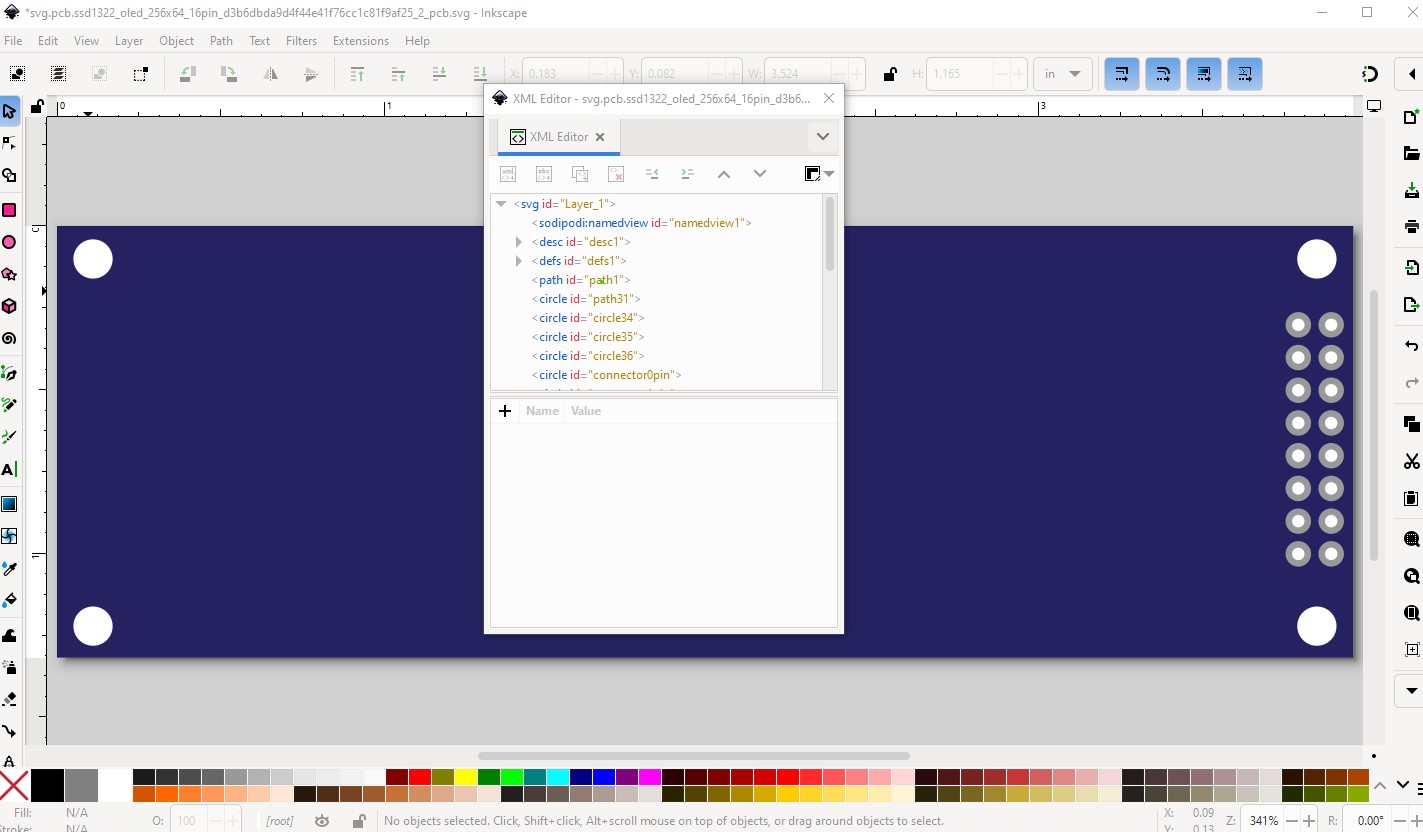
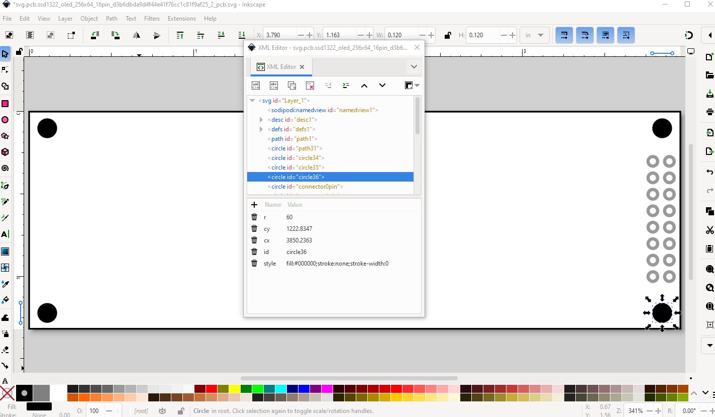
change the outline fill to none and add a stroke set to #000000 (black) with stroke-width 10. Change the mounting holes to black (as they will be on silkscreen only and not drilled.) This way if you want mounting holes you can drag the core parts pcb hole part in to the sketch, place it over the hole in silkscreen and set the size appropriately. If you don’t want mounting holes do nothing and they will only appear on silkscreen. You would need to modify the part to remove the mounting holes if they were drilled by default which is why this is done this way.
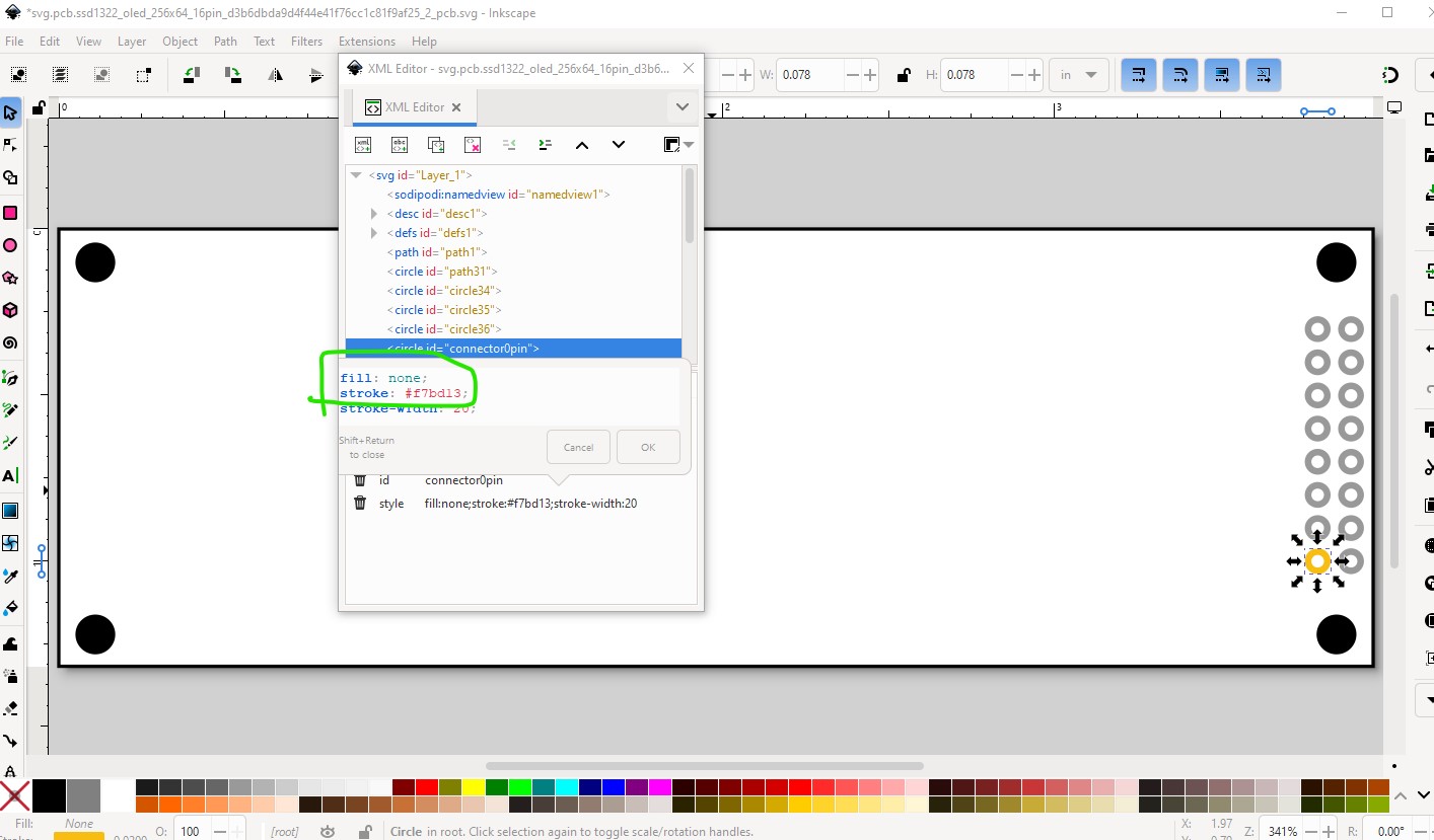
now change the pads to the correct color and set the fill to none (rather than the #ffffff (white) used in breadboard.
Then create the silkscreen group with the outline and 4 mounting holes.
then the copper1/copper0 groups with the connectors.

and we are done. I needed to change a number of things in the .fzp file (mostly to add the missing connectors as they all need to appear in all views by default.) Which creates this improved part.
OLED_256x64_SSD1322_16PIN.fzpz (7.7 KB)
edit: July 28 2025:
Replace the part with a corrected one as the pins are backwards. If you have downloaded the part please download it again. You will need to delete the current part in your mine parts bin and then shutdown Fritzing answering yes to the save parts and save parts bin prompts before Fritzing will let you load the new part.
OLED_256x64_SSD1322_16PIN.fzpz (7.5 KB)
This part has a changed moduleid and thus should load along side your original part.
Peter