Hello,
I am looking for the part for the SRD-05VDC-SL-C program (the part and not the module).
The only part I found had one of the 5 pants that was too small.
Or can I change the size of the hole on Fritzing?
Thank you in advance-
Hello,
I am looking for the part for the SRD-05VDC-SL-C program (the part and not the module).
The only part I found had one of the 5 pants that was too small.
Or can I change the size of the hole on Fritzing?
Thank you in advance-
If you upload the .fzpz file for the part you have, and tell me which hole is too small, I will modify the part to make the hole the correct size. Upload is 7th icon from the left in the reply menu. You can also in the sketch drag in a hole from the pcb section of core parts and change the size of the hole, however I’m not sure which hole (the parts original, the new hole, or both) will appear in the gerber drill file so fixing the original part may be the best bet.
Peter
SRD-5VDC-SL-C.fzpz (10.5 KB)
I thank you very much for your help.
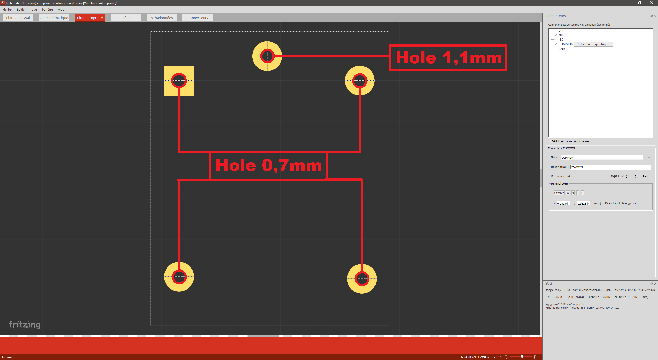
Here is the file and a picture to show the pant sizes.
For the crown there is no need to change it has to be thick enough for the pewter to hold the relay well.
Thanks again: D
Turns out there was so much wrong with that part that it was easier to make a new one. This part should do what you want and as a bonus is top-view (which means in breadboard it fits within the device footprint so it works correctly on perf board.) The holes are about .5mm larger than the pin sizes specified in the drawing. You need to print out the foot print at 1:1 scale and check it against a real part before ordering boards, as I don’t have an actual part, only the data sheet. The .6mm holes are 0.03in (7.62mm) and the larger one is 0.045in (1.14mm) in the gerber output.
edit: Correct the pcb footprint (the hole sizes were wrong!) to be 1.3mm as recommended in the data sheet.
SRD-5VDC-SL-C.fzpz (4.9 KB)
Peter
Hello, I do not know if you will be alerted by this message but there would be a very small touch up to do on the lower legs. Would it still be possible to help me please?
Sure, what needs to change?
Peter
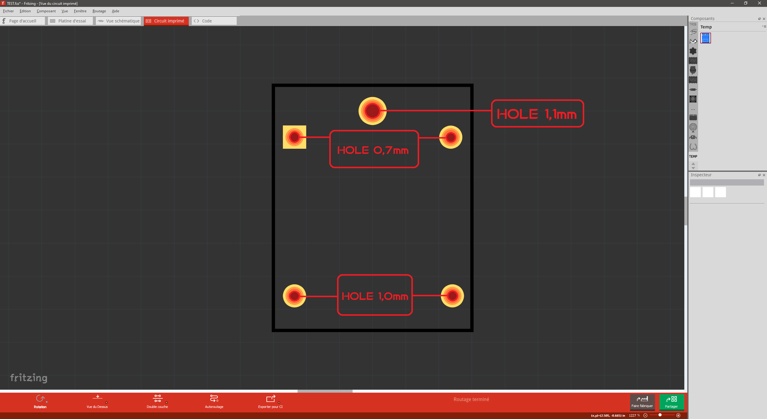
I made a very silly mistake in my measurements and it turns out the top three legs are fine but the bottom two legs are 1mm wide. Sorry to bother you again with this ^^
OK, I found the data sheet for the relay here:
http://www.songlerelay.com/Public/Uploads/20161104/581c81ac16e36.pdf
and used the recommended hole size of 1.3mm for all 5 holes (and verified the hole positions to the data sheet which we had correct.) I have replaced the part above with a corrected version, so download it again and all should be well. The gerber drill.txt file indicates the holes are all 0.051180in which is 1.3mm.
; NON-PLATED HOLES START AT T1
; THROUGH (PLATED) HOLES START AT T100
M48
INCH
T100C0.051180
%
Peter
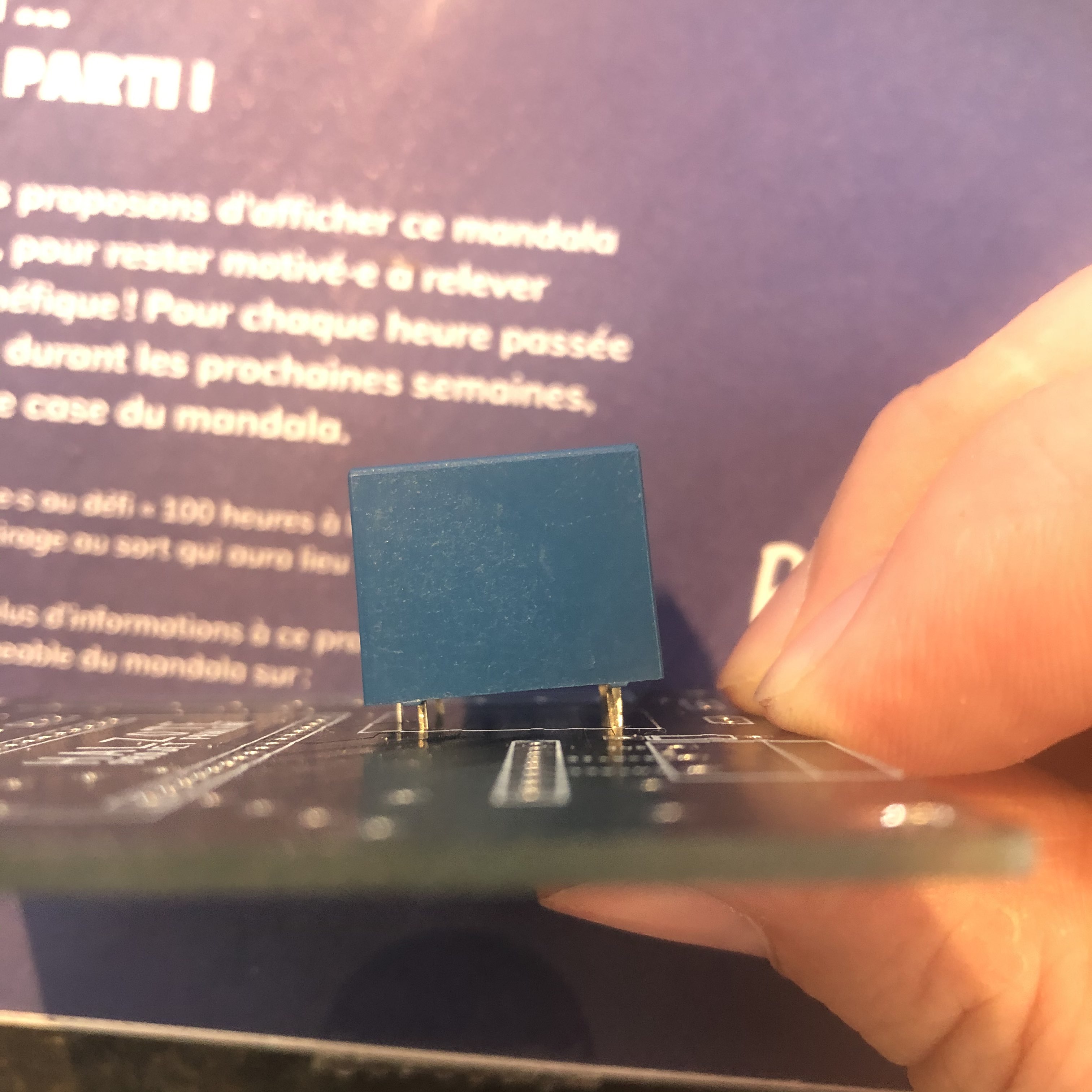
I have the exact same mark as the spec sheet and I think they must be having production issues because it doesn’t fit into the board I made made. It’s really the two hind legs that don’t go through.
That will be because in the original part, the rear two pins holes are too small (0.030 in around .75 mm when the pins are 1mm) The new part has 1.3mm holes as the data sheet recommends and thus should work correctly.
Peter
OK thank you very much then 