Name of the part
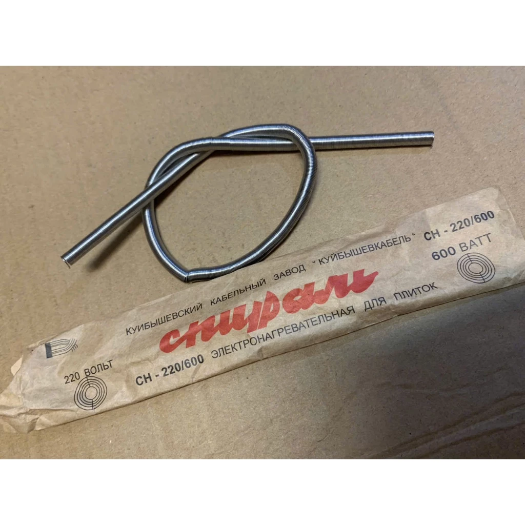
Spiral Heating Element CH-220/600 (for electric hot plates)
Previous work, similar parts
None specifically found for this exact visual representation. Generic power resistors are sometimes used as a stand-in, but a dedicated part with a coil graphic would be preferable.
Top view
The part is a coiled resistive wire, forming a loose spiral.
Connectors: Two, one at each end of the resistive wire.
These would typically be bare wire ends for connection via screw terminals or crimp connectors in an appliance.
The image provided:
Datasheet
No formal PDF datasheet is available. The information is derived from the product packaging shown in the image:
- Manufacturer (implied): КУЙБЫШЕВСКИЙ КАБЕЛЬНЫЙ ЗАВОД (Kuibyshev Cable Factory)
- Brand/Product Line: “КУЙБЫШЕВКАБЕЛЬ” (KuybyshevKabel)
- Product Name: СПИРАЛЬ ЭЛЕКТРОНАГРЕВАТЕЛЬНАЯ ДЛЯ ПЛИТОК (Spiral Electric Heater for Hot Plates)
- Model/Type: CH-220/600
- Voltage: 220 ВОЛЬТ (220 Volts)
- Power: 600 ВАТТ (600 Watts)
Type
Resistor (R) (Heating elements are essentially power resistors)
Footprint
This is a wire-ended component. It does not have a standard PCB footprint like SOT23-5 or TO-220.
For PCB view, it would require two through-hole pads for connecting the wires. The spacing would depend on the application. A generic two-pin header footprint with appropriate pad size for high current might be suitable, or simply two customizable pads.