Hi there! So I recently started learning how to use this program so I don’t really know the basics…
But could anyone help me find the datasheet part of the program? I would like to check out the pinspacing of my project.
Plus, how can I connect an resistor to a buzzer and an esp? And how can I add and connect a battery to the same component?
And, by the way, can y’all check if I’m doing this the right way please?
Thank you so much!
There isn’t a data sheet part of the program. The individual parts have data sheets from their manufacturer (sometimes included in the part as a url but it is optional.)
The pin spacing in breadboard will typically 0.1in (the same as the breadboard) and schematic is the same. Pcb is whatever the pin spacing on the actual device is.
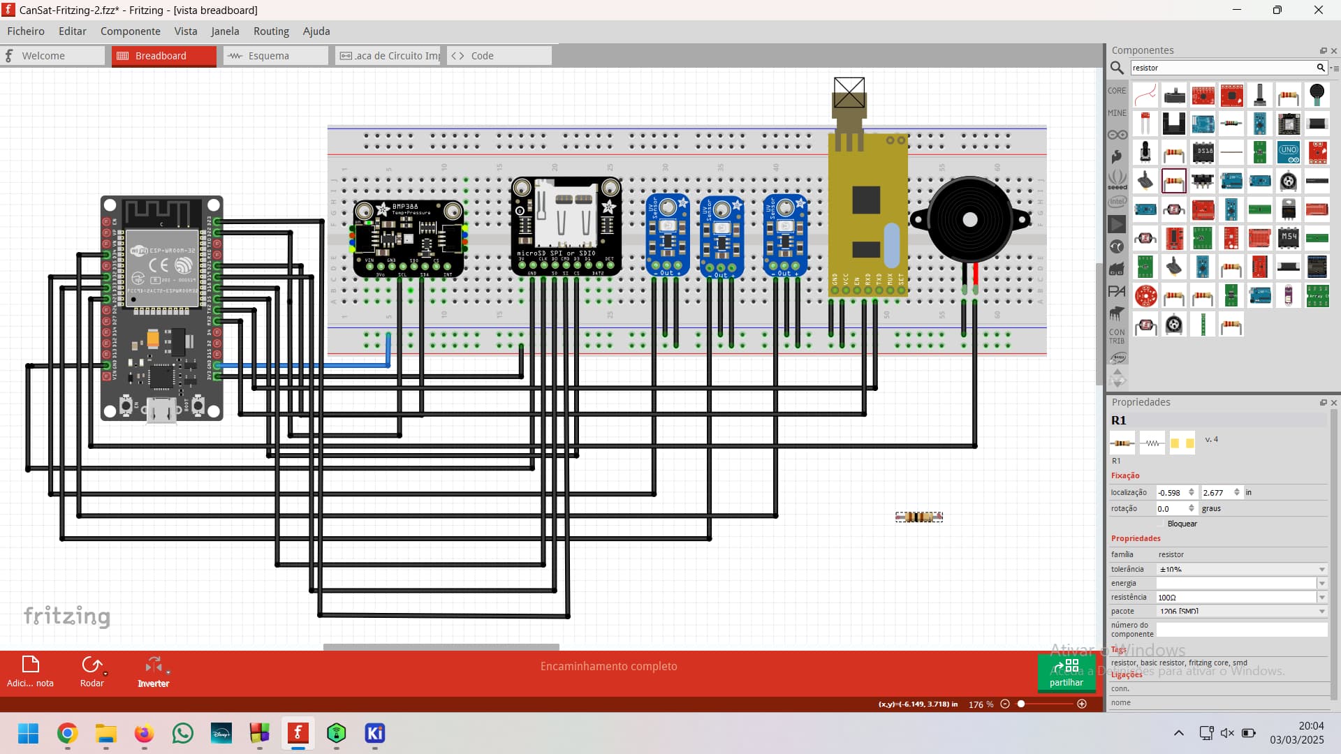
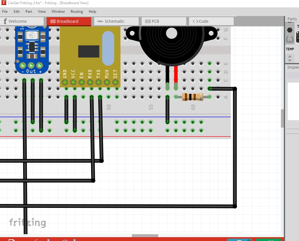
drag the resistor in your sketch on to the breadboard, connect one end to the buzzer and move the other end to the other end of the resistor like this
Note you need to determine how much current the output pins of your ESP can source and sink and determine how much current the buzzer takes (and if that is less than what the ESP will provide, if it is not you need a driver between the output pin and the buzzer.)
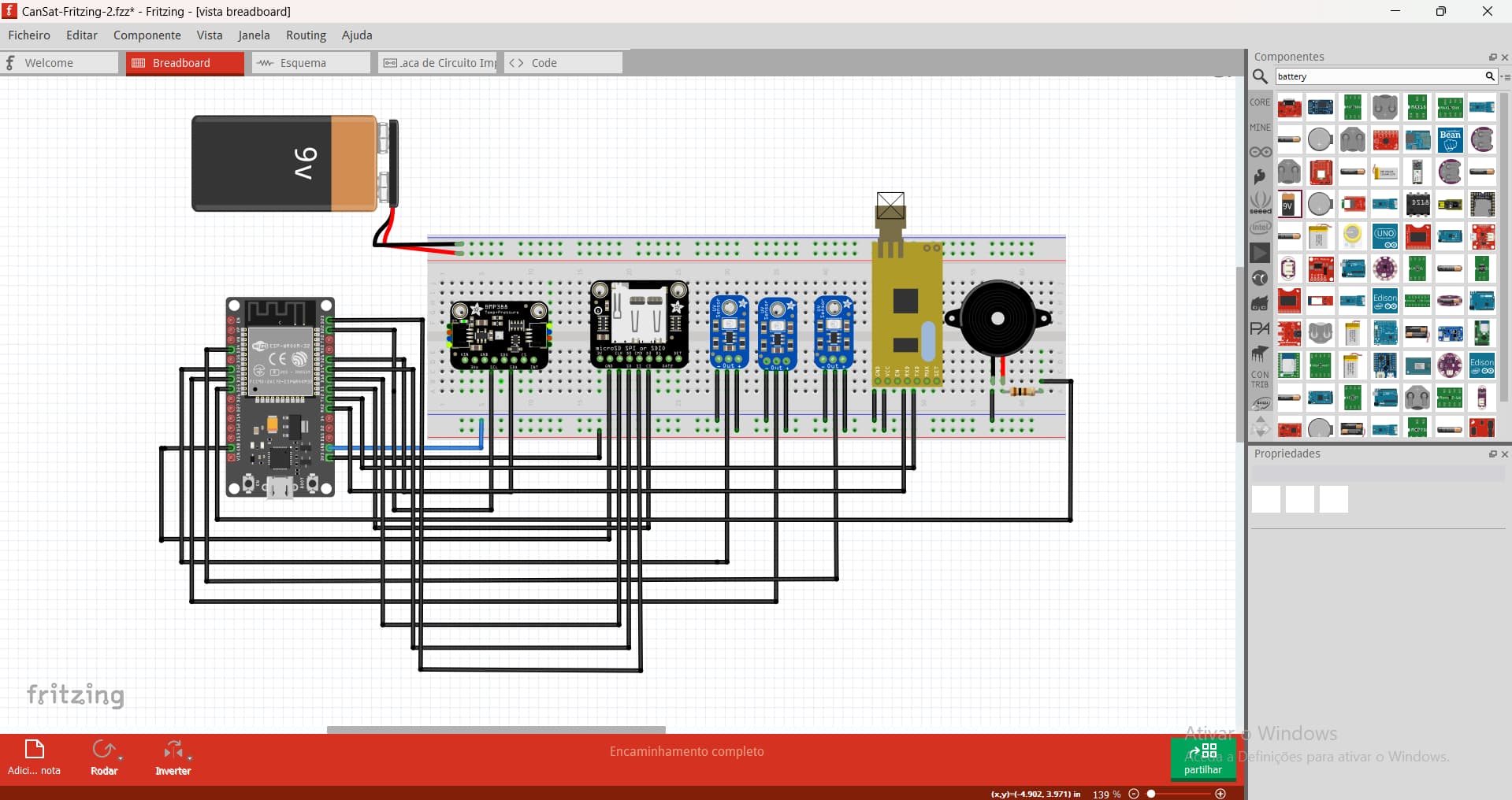
You need to determine if the ESP board will accept a battery, if so what voltage. If it won’t and wants a fixed voltage in you would need a boost/buck regulator module between the battery and the fixed voltage power pin. There are batteries of various kinds in core parts (search for battery in the parts search window.)
Peter
1 Like
Thank you so much for all the help!
Could you please check if there are any mistakes this time?
Because when I tried to press “Design Rules Check” on Routing, it gave me an error on the pcb, but i just can’t find what’s wrong…
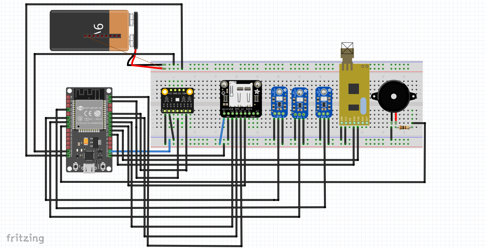
You would need to upload a copy of the sketch (the .fzz file, upload is 7th icon from the left in the reply menu.) Images are basically useless when trying to diagnose problems. If you click on an error in the DRC window it will select the trace where the error is and light the trace red at the point where the error is (you sometimes need to zoom in and go along the trace to find where the red mark is.) From the image above your battery isn’t connected to anything. There needs to be a wire from the negative terminal to ground and the positive terminal to VIN on the ESP32 board (which currently has no connection to anything.)
Peter
1 Like
Alright! Thank you so much for your help, once again
Here’s the file of my project:
CanSat-Xanthoria-Fritzing-2.fzz (115.8 KB)
I just fixed the battery situation by the way ![]()
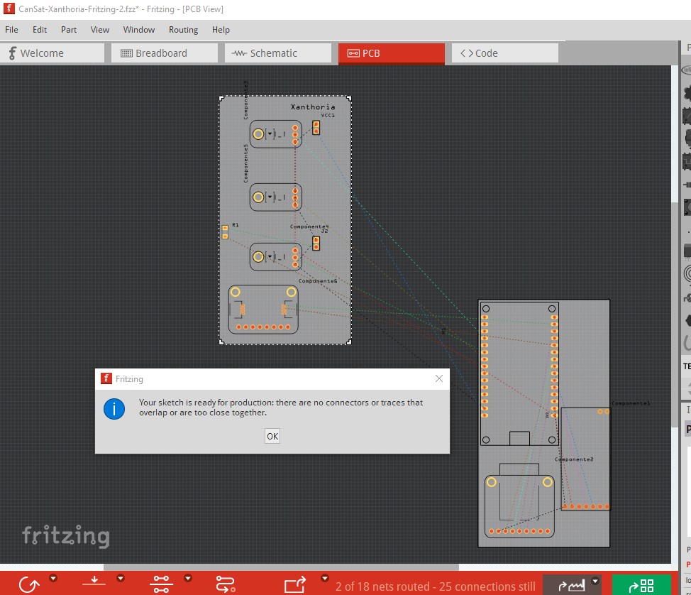
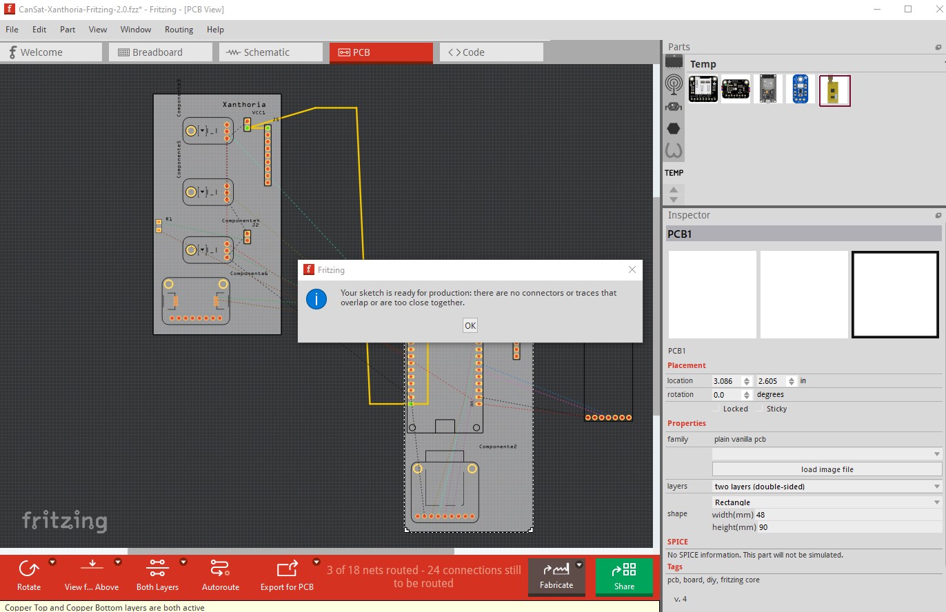
Pcb isn’t currently routed so DRC passes (because there is nothing to check):
or did you perhaps get the wrong sketch? You will need headers to make the connections between the two boards as well. Traces can’t cross between boards.
Peter
1 Like
Got it! So where and how should I put the headers to connect both boards?
I spoke too soon, the other board has a DRC problem (probably a broken part)
I’ll fix up the radio part so it passes DRC. As to the headers
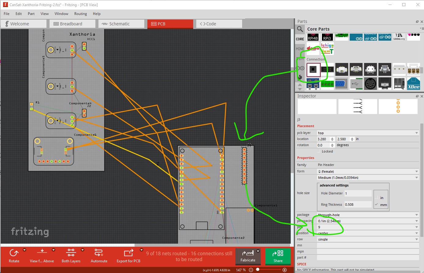
this will work (the other board needs the same connector added to give the wires between boards somewhere to connect, that can be either wires or headers which attach to wires between the boards. By default the header will be 2 pin you need to increase that to 9 to cover all the traces between boards (which I set to count the number.)
Peter
1 Like
Thank you so much for all the help! This has been so valuable to me and my team!
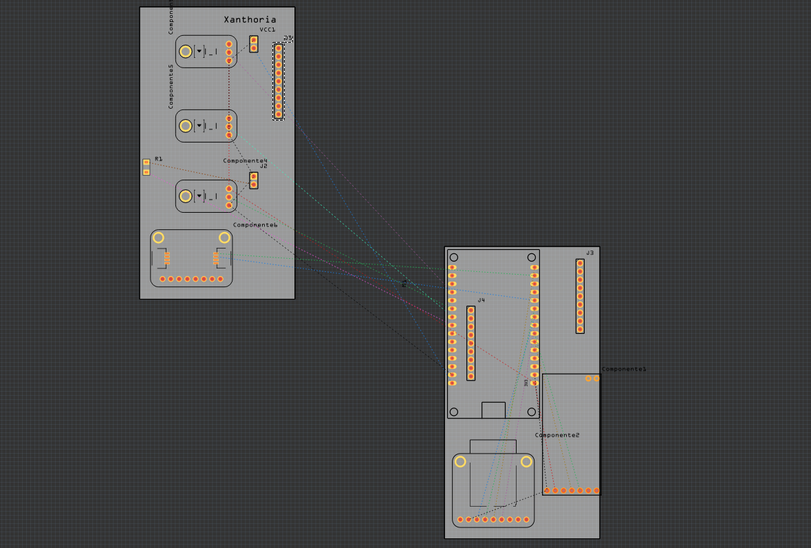
One last thing tho, I just positioned the headers on both boards… now all i have to do is connect the 9 pins from one board to the other 9 from the other board? Or did I get it wrong?
Here’s a picture of how it has turned out btw:
So you now need to do this:

here I made a trace (the brown trace on bottom layer) for the interboard wire. Then I created traces on the top layer (yellow traces) to connect to the two connectors one on each board. They need to connect to the same pin on each connector although to make trace routing easy you can put the wires in any order on the two connectors although it is best if they connect to the same pin on each of the two connectors. The brown wire outlined in red is the wire between the two headers.Note if you want to use the mounting hole on the ESP board (which is not drilled by default) you will need to move the trace on the bottom board as the mounting hole would break the trace as it is currently routed. The APC220 part is misconfigured (it lacks the top layer definition) and is thus broken. I’ll post a corrected version in a bit.
Peter
1 Like
OK here is a corrected part for the APC220 which now passes DRC. A delete minus of the old part will leave the traces and allow you to connect the new part by dragging the wires on the the new part (in all views!) @leoberger you will be wanting this part as well as the one you have is broken.
APC220 with antenna.fzpz (4.6 KB)
Peter
1 Like
Hi again! So, I just added the antenna, but the error is still showing on one of the PCB. Do you think you can help me fix it?
And thank you so much for all the help once again!
CanSat-Xanthoria-Fritzing-2.0.fzz (116.3 KB)
While the trace in red shouldn’t be implemented (it is not on the board and the end that is on the board would appear as copper!) for me on Fritzing 1.0.4 both boards pass DRC.
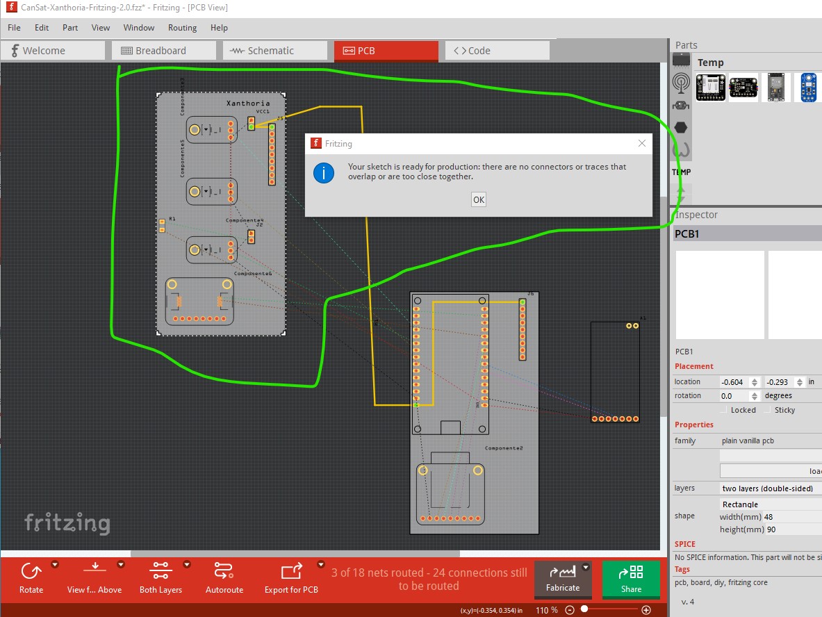
That DRC error are you getting?
Peter
1 Like
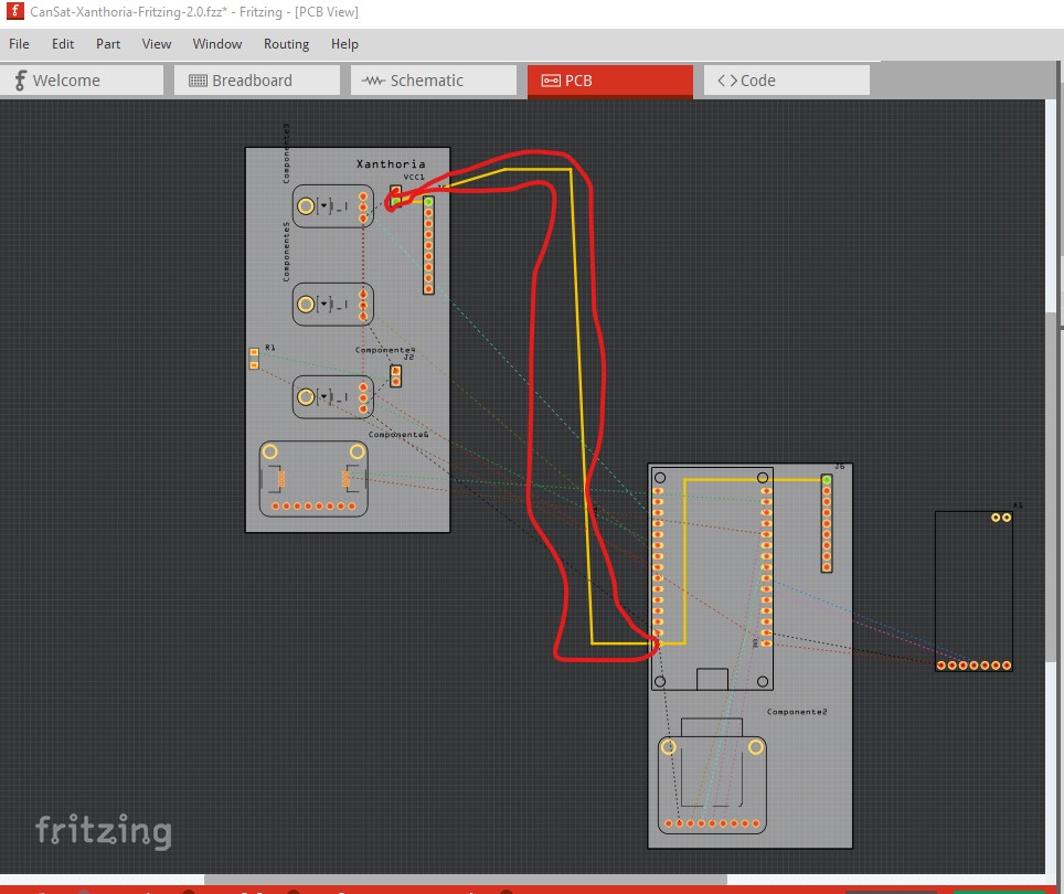
So it’s better if I just delete the trace in red?
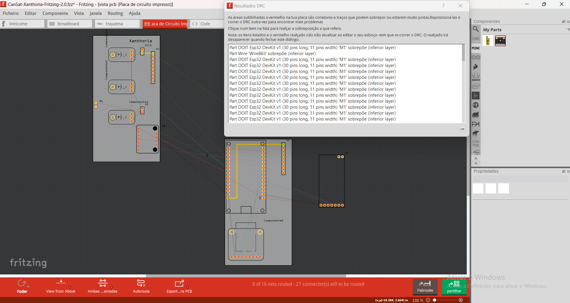
And this is the error that I’ve been getting:
The message appears in portugueses but it’s basically saying that the red areas might be too close or on top of each other and that might be affecting the circuit
It appears to be complaining about the pads on the ESP32 board (which would indicate a part problem) yet it does not complain for me on Fritzing 1.0.4. First thing to do is check your DRC settings
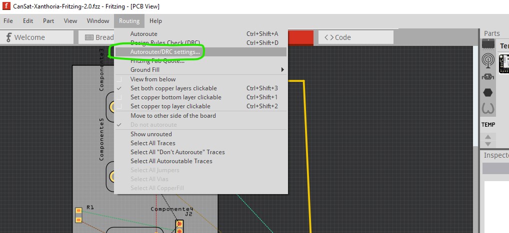
which brings up this
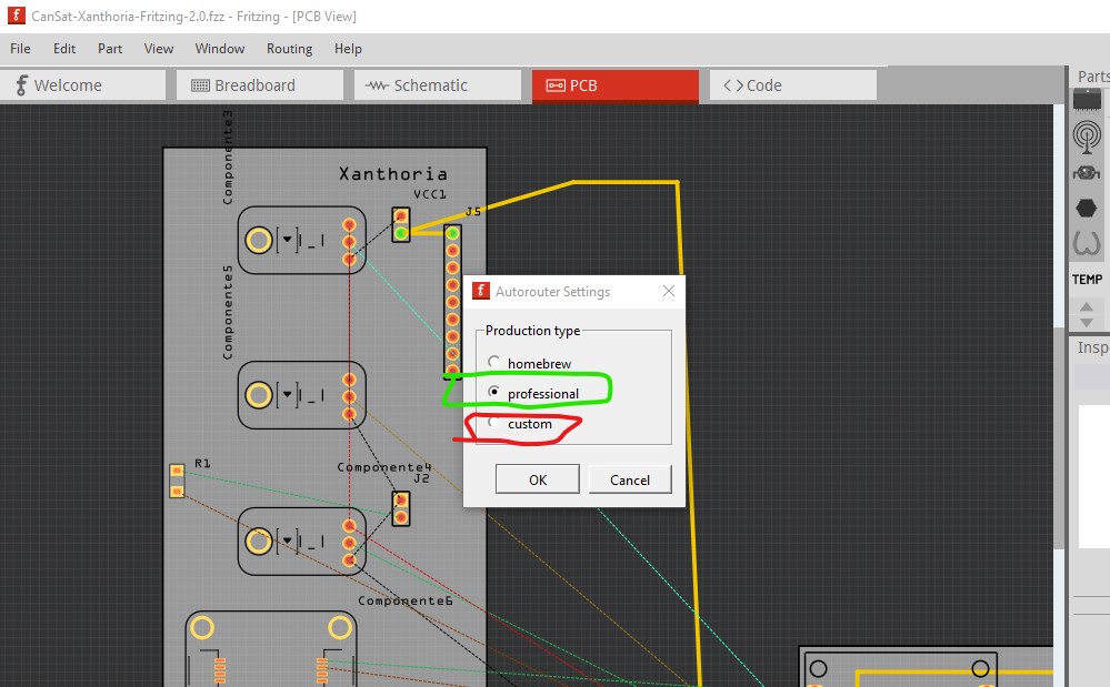
you should be set for professional rather than homebrew or custom (assuming you are having boards made by a board house rather than etching yourself.) On a side note here is what will happen if the trace circled in red is left in the sketch. This is the gerber output of your sketch which is what the boards will look like when produced.
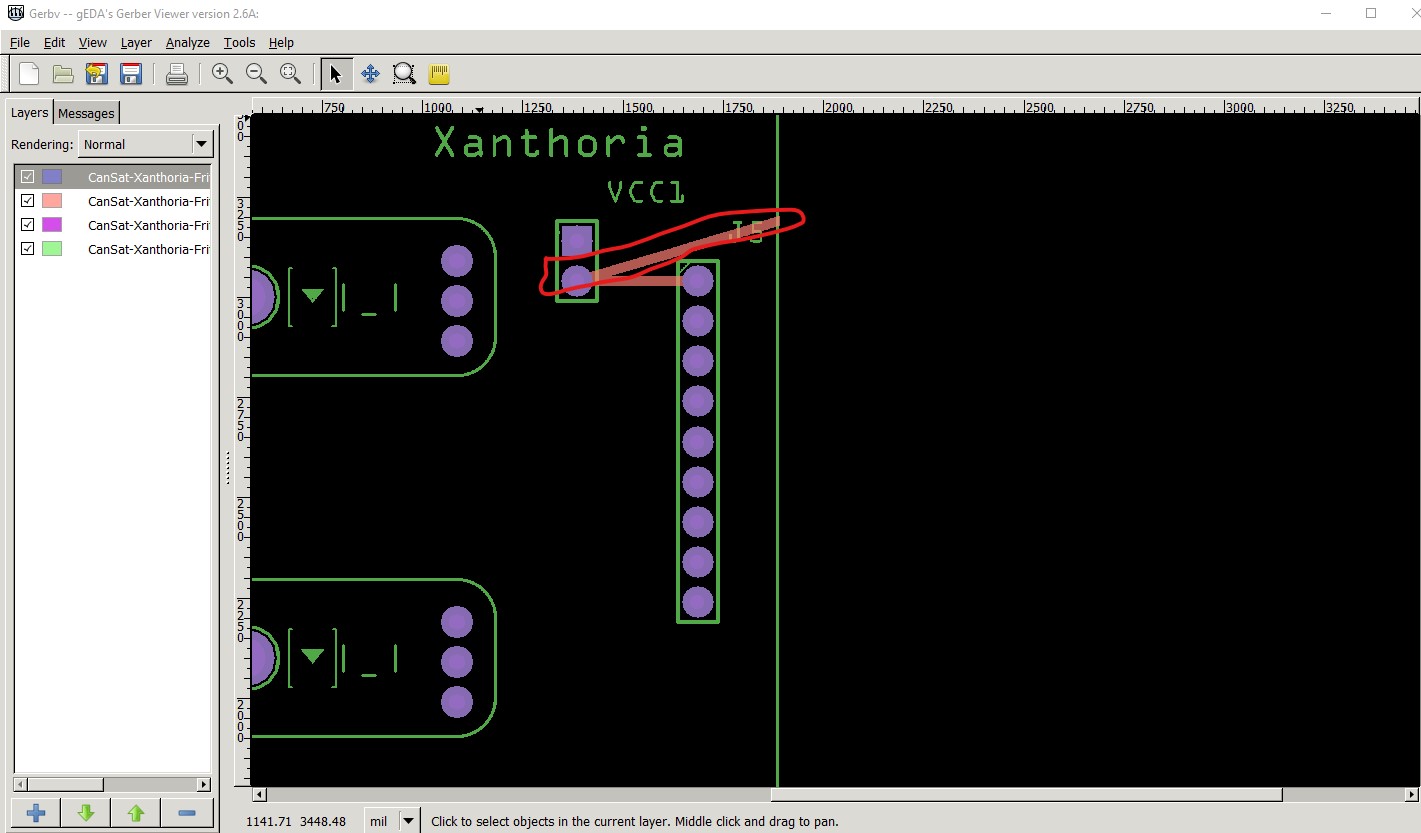
as you see you will get the part of the trace between boards that is on the board that truncates at the board edge (which is not what you want.)
Peter
1 Like
I decided to eliminate the “wire” that connected the two boards, as this will be a physical connection (as you said before).
So this is what I have now:
But I keep getting the same error… and, as I checked, the settings for the DRC are correct, so I don’t know what to do…
Besides, I just added the BMP you had sent (thank you so much for that by the way) and I can’t figure out how to connect some of the wires… so could you please check if this is well done?
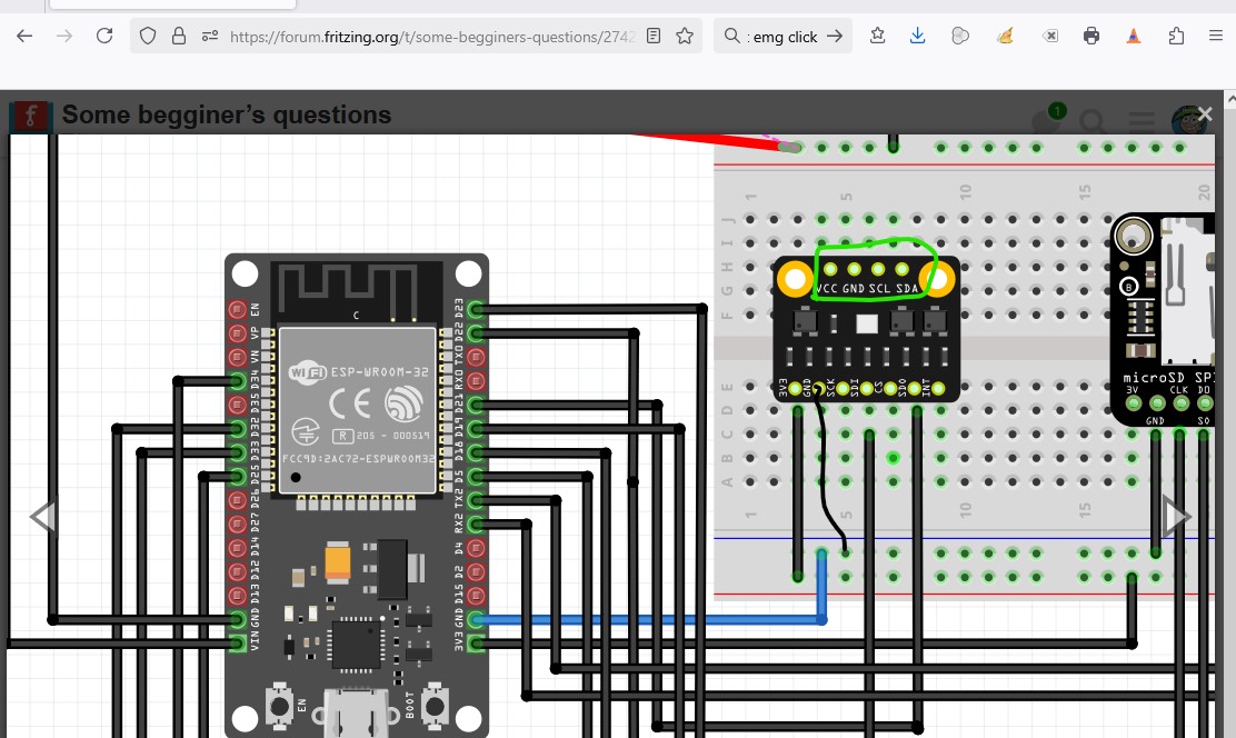
The bmp board needs a ground (indicated by the black wire in the image). I don’t know anything much about it, but on the wiki page at DFR they show the connection being to I2C on the top 4 connectors circled in green. I expect you can get the data from the bottom 7 pins, but I don’t know how.
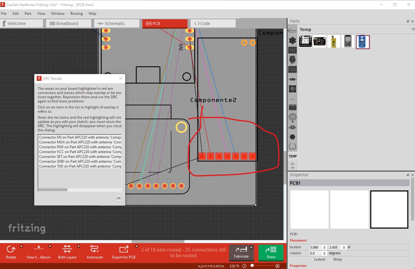
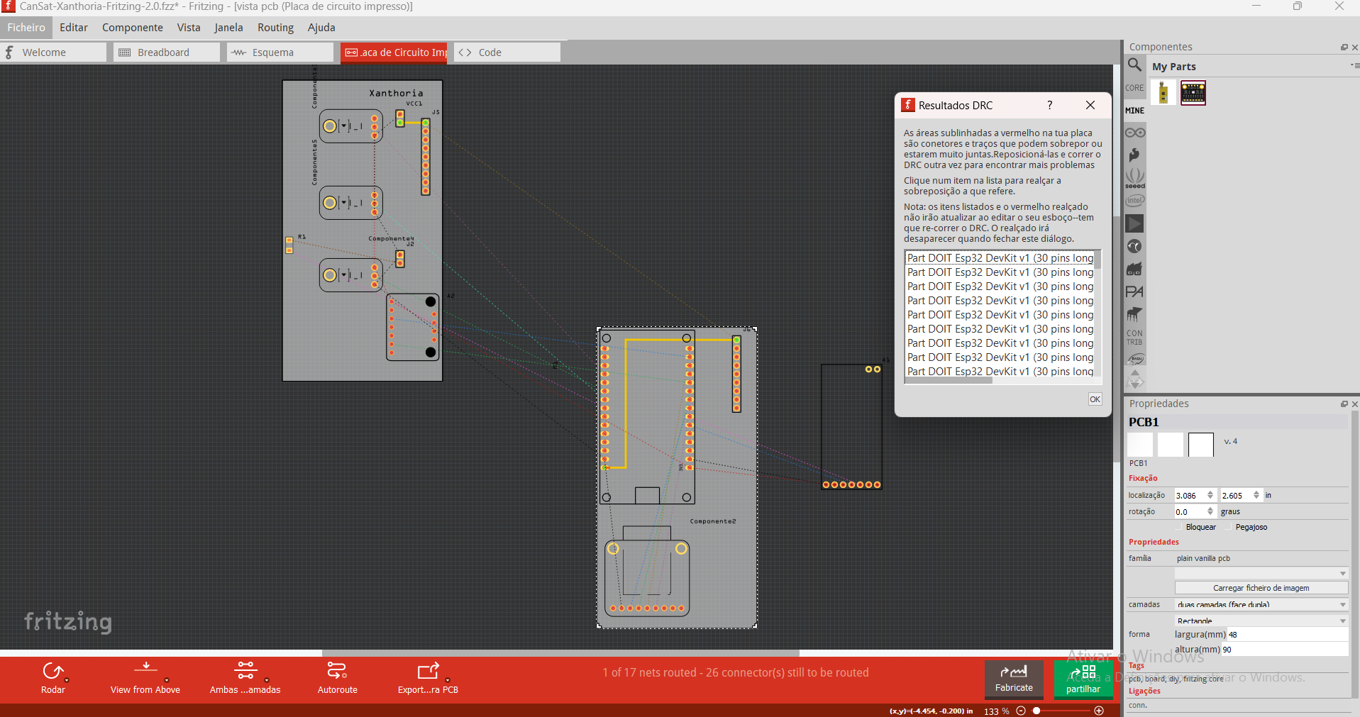
The DRC error is puzzling because it isn’t happening for me. Could you please expand the DRC window (click and drag the window edge) so I can see the entire error message that may give me a clue. Here I intentionally moved the wire to overlap the pad on the micro to cause a DRC error as an example
Circled in green you can see the red on the pin of the micro which indicates the source of the error. I’m not seeing any red on the micro part but that is what it appears to be complaining about. The full error message may tell me something though. This doesn’t happen for me on Fritzing 1.0.4. What Fritzing version are you using as well? It could be a bug in an older version I guess (I have most of the older versions around to try.) Ah! On Fritzing 0.9.3b I get the errors:
It is complaining about the pads. I’ll have a look at the part and see if I can fix it up. Looks like a bug that got fixed in a later release. If you can updating to version 1.0.4 is a good bet because there are a lot of bugs that have been fixed (but it costs an 8 euro donation, or building from source which is not easy!) I’ll see if I can fix the part in some way.
Peter
1 Like
Thank you so much for all the help!
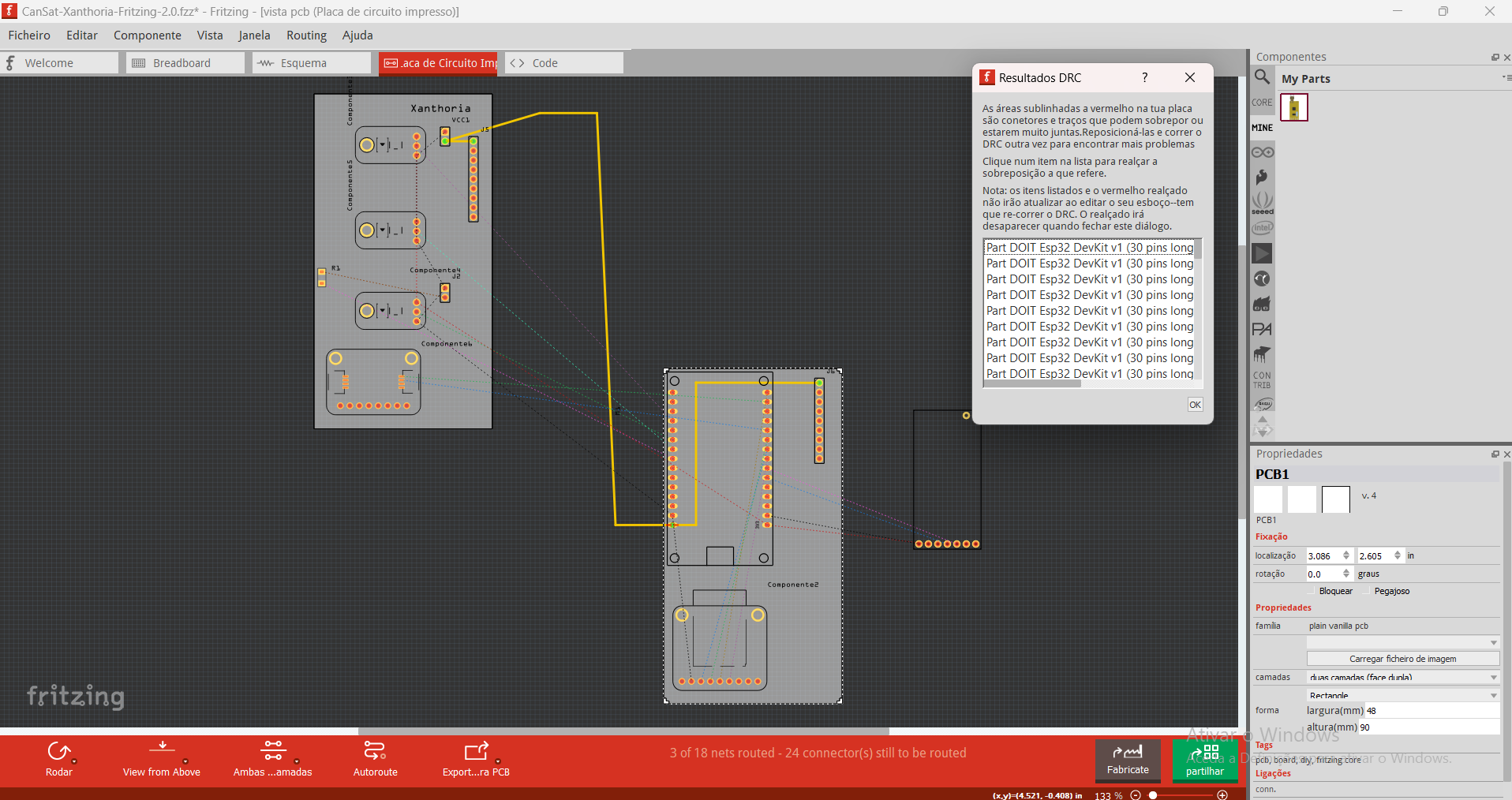
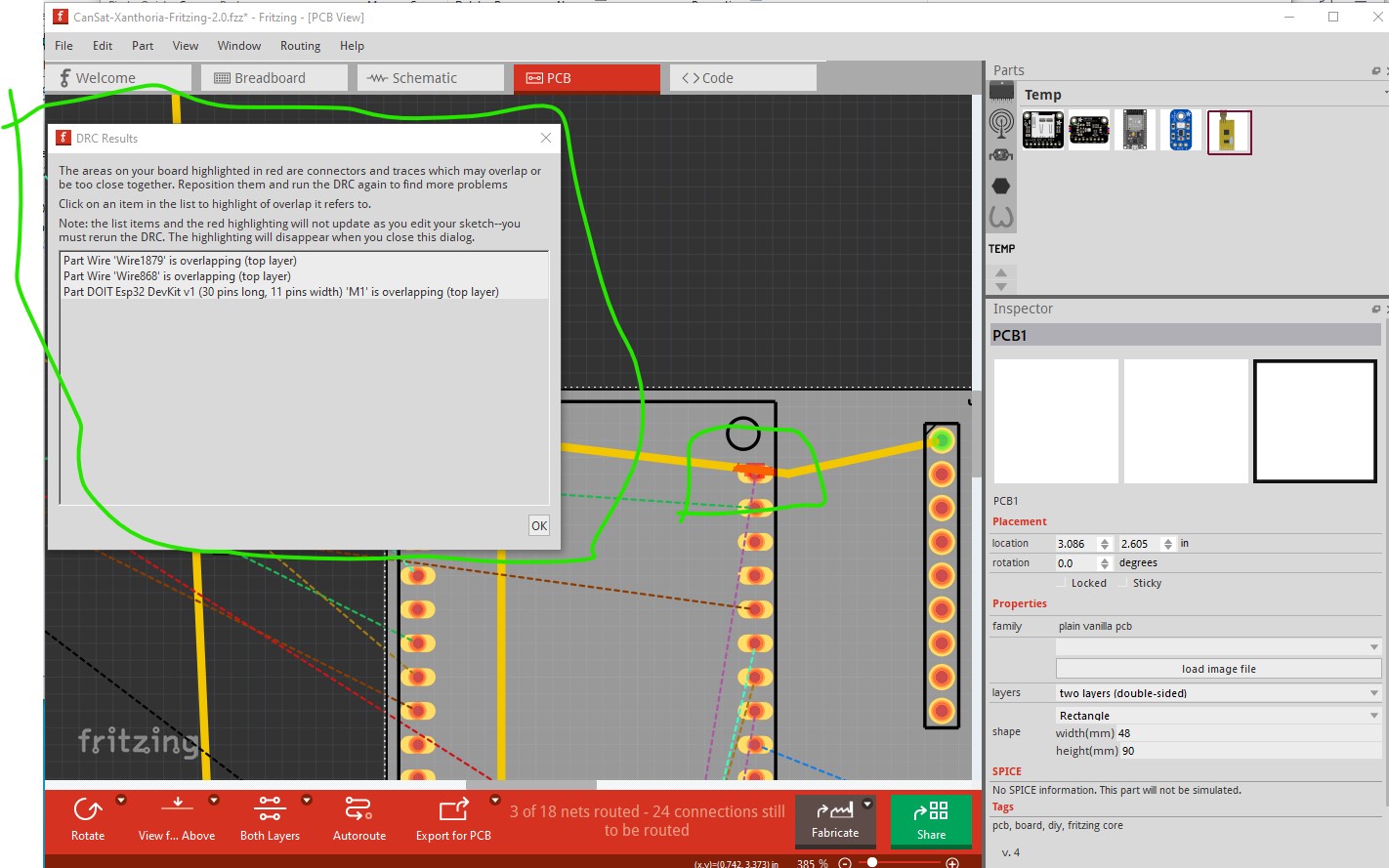
Here’s the full error message I’ve been getting:
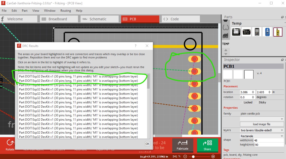
And this one too:
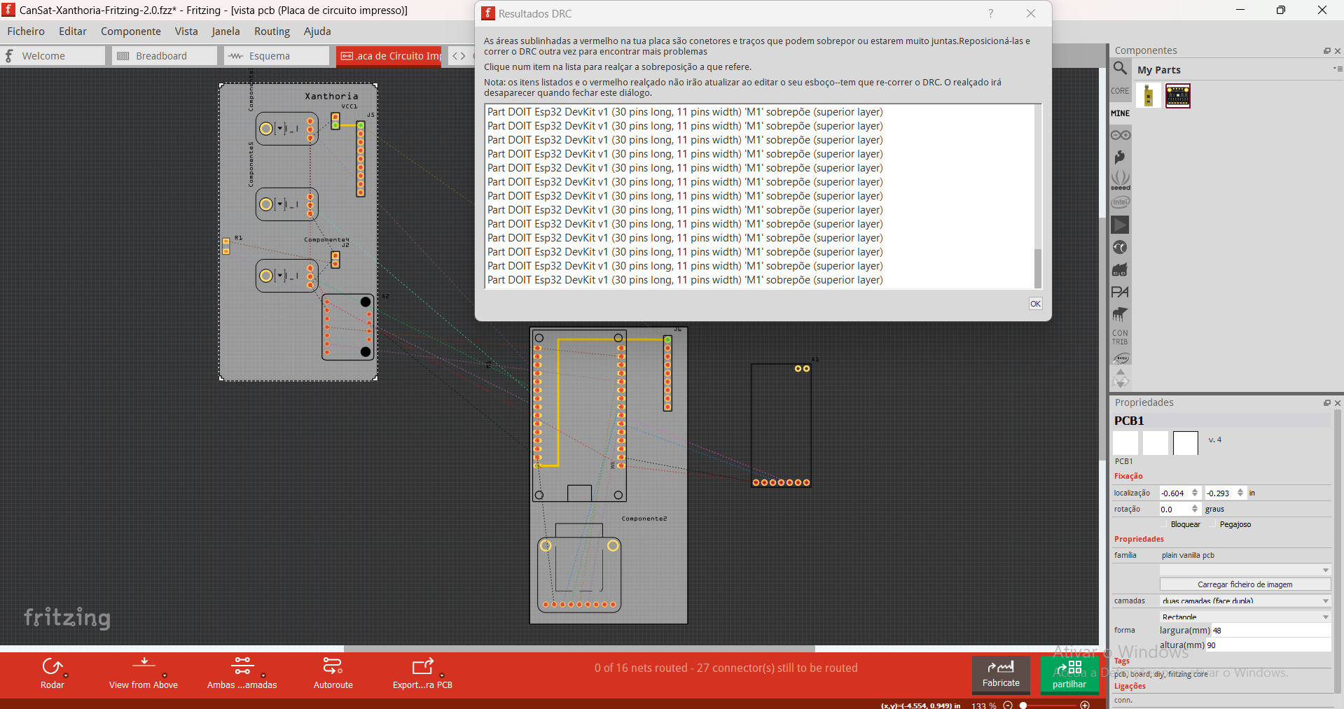
This is the version I’ve been using by the way- Version 0.9.5
And here’s the whole project if that helps a bit more:
CanSat-Xanthoria-Fritzing-2.0.fzz (101.2 KB)
OK I don’t have a copy of 0.9.5 but by 0.9.6 DRC works. In any case I know what it is complaining about, the path that makes the narrow pins is what is overlapping (because they aren’t part of the same net.) This ESP part has standard header pins and passes DRC on 0.9.3b.
DOIT Esp32 DevKit v1 (30 pins long, 11 pins width)-circlular-pins.fzpz
You won’t be able to run traces between pins (you may be able to with 8mil traces if you need to though, no I just tried it and it fails DRC.) but that shouldn’t be an issue I don’t think.
DOIT Esp32 DevKit v1 (30 pins long, 11 pins width)-circlular-pins.fzpz (33.5 KB)
You will need to delete the copy of the DOIT Esp32 DevKit v1 (30 pins long, 11 pins width).fzpz in your mine parts bin and then shutdown Fritzing answering yes to the save parts prompt and yes to the save parts bin prompt to really delete the part and then restart Fritzing and load the new part and place it in the sketch then move the wires in all views to restore the connections. I did all of that in this modified sketch which should now work for you and pass DRC.
CanSat-Xanthoria-Fritzing-2.0-new-esp-part.fzz (100.1 KB)
Peter
1 Like
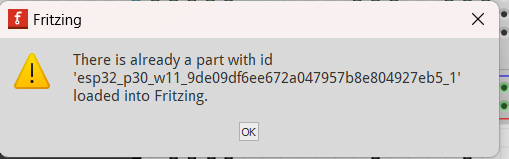
I wasn’t able to download the esp you sent, because I kept getting this error message (even after I tried to delete the esp I had inserted initially)
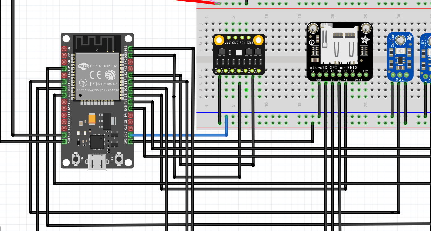
By the way, I noticed the microSD didn’t had any wires connecting the “3V” with the corrent that was passing through the breadboard so I added that…
But could you check if it is correct? And by the way, do you think it’s necessary to connect the VCC entrance of the BMP with the energy connection that the battery is supplying?