Since it seems there’s no fritzing parts I can modify for my needs, I’m trying to make the BTS428L2 part myself. I’ve modified parts before without issue dozens of times, but today, it’s beating me!
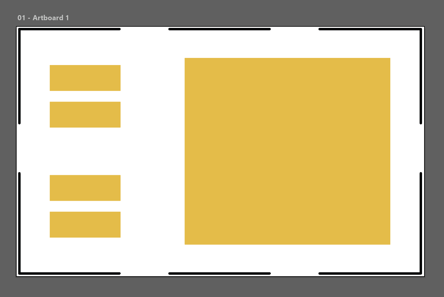
In illustrator (and inkscape) my SVG looks like this:
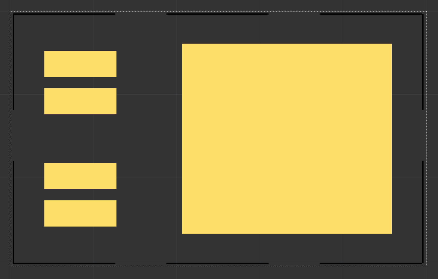
I can’t figure out why the hell the pads on left are overlapping! It does seem to pass DRC when I run it but I don’t understand why it shows like this as soon as I import the SVG. It also shows the same when placed onto a PCB.
Apologies for the delay, only just got back to this topic!
@KjellM is correct - it’ must be an issue with stroke width! Even though inkscape and illustrator had no stroke width - the SVG code didn’t have stroke-width=“0” or stroke-width=“none”
When I edited the SVG in a text editor and added that to the pads, it does now show correctly!
So seems the stroke width poor standardization was the issue here.
Seems like a bug to me, it should ideally work like “if there is no ‘stroke-width’ set, assume it is NONE” but currently seems like if there’s no stroke-width set then it defaults to a fixed pt width.
Thank you both for your replies and help.
I’ve learned something new (that the absence of stroke-width is not the same as specifically stating no stroke width) - this can now be closed as resolved! Thanks again