shematic_v1.fzz (131.5 KB)
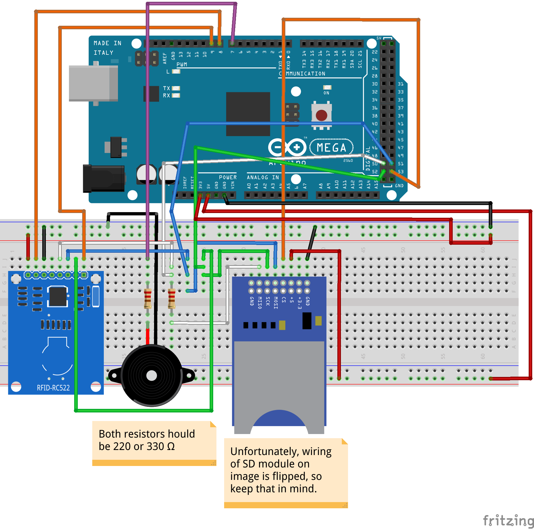
Well yes you could certainly make schematic cleaner (since schematic is currently not routed at all!) Assuming you really mean can you clean up breadboard (the view in the image above) the answer is maybe somewhat. The odd part is the note on the SD card module that the wiring is flipped which it does not appear to be from the labels on the pins. The RFID module which appears to be 3.3V is being driven from a 5V Arduino without level translation which is unwise. All in all it is unclear what you are asking or are trying to do.
Peter
@vanepp Thanks. Well, when I say flipped I mean that module I buy came with “upside-down pins” compared to this, I mean, it’s flipped over when it’s placed on the breadboard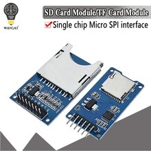
. Also, RFID module is connected directly to Arduino 3.3 V, I don’t see a problem with that. The reason some wires are in weird angles is that I didn’t want to hide pin numbers with them.
EDIT: My autocorrect has gone crazy, LOL.
As long as you use jumper wires to connect to the correct pins on the Fritzing part that should be fine.
Yes the RFID module is powered by 3.3V, but the problem is that the signal lines are being driven by a 5V Arduino pin without level translation. The logic level of the pins must also be limited to 3.3V, driving them with 5V will appear to work but will damage the pins on the RFID reader and may be pulling the 3.3V supply from the Arduino up to 4V or more. The 3.3V output on a Uno is only good for about 30ma and a I/O pin will source 40ma.) The higher than 3.3V power source may also damage the RFID device. You need to use an I2C capable level translator like this one from Adafruit to protect the RFID reader (or change to a 3.3V Arduino like a 3.3V Nano.) Note I2C has some issues that mean not all level translators will work with it, so you need one that is specifically I2C compatible which the Adafruit one says it is.
SD cards are also 3.3V but it looks like your interface card has built in level translation (although you should check that it does!) The easy solution would be to use a 3.3V Nano in place of the 5V Uno as then you don’t need level translation.
Peter
What is the maximum current draw of the RFID module? The 3.3V output from the Arduino is not very powerful. It is good for up to 150ma. RFID includes a radio. When it sends a read pulse, the power requirement probably jumps significantly.
Yes I know, but I wrote that so that if I publish my project, people are aware of that they can’t connect it verbatim as on the schematic.
Well, I’ve been using this straight for many hours and nothing damaged so far. Also, many tutorials on the internet doesn’t show that level translator is needed and nobody reported that they fried something.
EDIT: The reason I am trying to avoid level translator is maybe a bit stupid, and it is that I don’t want to wait for it to arrive overseas. But, can I use resistors instead of level translator?
@microMerlin I have no noticeable problems with reading. Maybe only problem is that reading distance is limited, but for prototyping and non commercial use it’s ok.
As noted you can use a 3.3V Nano Arduino CPU to avoid the issue ( but that probably has the same problem with deliver.) but with a 5V CPU the problem is still there. There is a substrate diode that clamps the input pin to the 3.3V power supply that will cause the 5V input signal to high current and depending on the current available to the 3.3V power source either drag the 3.3V power supply higher than 3.3V. It was up at around 4.2V when I accidentally did this on a Arduino Uno with a 74hc125 rather than a 74ahc125 (the 74ahc125 does not have the substrate diode and the input pin will stand 5.5V at the input even when powered at 3.3V.) and damaged the CPU I/O pin on the Uno. So it will appear to work but will probably eventually cause damage. The safest bet is to either run all the devices at 3.3V or use a level translator, and as noted I2C is somewhat special and needs a special kind of level translator some of them don’t work well with I2C.
Peter
@vanepp
Ok, I will try to limit my testing time for now (plug the Arduino to PC - test and find error in code - unplug from PC - fix the code - repeat), but if I will need RFID in permanent project, I will consider buying the level translator. Also, I think that when I have many modules and sensors connected to Arduino (what I am planning to do), there is some voltage and current drop, which is good for the RFID module, am I right?
@vanepp
Even if I decide to buy a level translator, how could I use this one? It’s only four channel.
I didn’t answer the question of will a resistor do for the level translation. In this case a series resistor should help some, in that it will limit the current flowing between the 3.3V and 5V power supplies (which is the main source of trouble), at present you have a circuit that looks like the top part of this:
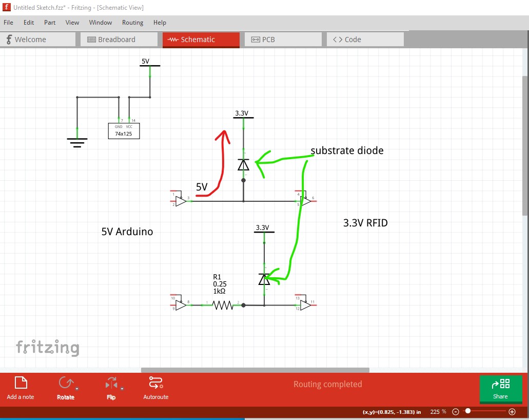
The current case is the top of the drawing when pin 3 on the left is at 5V it is a short through the substrate diode from the 5V to the 3.3V power supplys. Depending on how much current the 3.3V supply can source, if the 5V is stronger (true on the Uno at least) then the 3.3V supply will be pulled up to about 4V which may damage devices that are only rated for 3.3V. If both supplies have a lot of current available, the power supply voltages will remain the same, but the substrate diode will be taking the entire current load and likely burn out (perhaps taking the chip with it.) The 1K resistor in the bottom drawing limits the current through the substrate diode to a lower value, the downside to that is that it will also change the logic level voltages which in this case may not matter. The I2C connection is bidirectional, sometimes the Arduino drives towards the RFID (the case shown here) and then the RFID drives towards the Arduino which can cause a different problem (which is also solved by the level translator.) The RFID will present 3.3V towards the Arduino, but the Arduino input high level threshold may not be low enough. On TTL a high is anything above 2.5V on CMOS it can be much higher (such as 3.5V on a 5V gate) if that is the case then the RFID will not reliably drive a 1 towards the Arduino. The level translator takes the 3.3V input and produces a 5V signal to the Arduino which solves that problem.
The I2C connection only needs two of those channels, one for SDA and one for SCL. The RFID side of the level translator is attached to the side of the level translator that has VCC set to 3.3V and the Arduino pins attach to the side of the level translator that has VCC set to 5V. The 3.3V input signal is translated to a 5V output signal to the Arduino and the 5V input signal is translated to 3.3V output to the RFID keeping both of them happy. Any of the I2C devices that are on 3.3V need to attach to the 3.3V side of the level translator. If there are also 5V I2C devices they would connect directly to the Arduino pins.
Peter
1 Like
@vanepp Wow, thanks a lot for a long answer and explanation.
What I am suprised from the beginning is that the RFID module has such a low voltage difference tolerance, I mean, it’s only 1.7 V difference…
EDIT:
I understand that, but there are four more pins that are not I2C (all together, six). Does that mean that I would need two level translators?
I went and pulled up the rfid module and discovered this at this web site:
" The operating voltage of the module is from 2.5 to 3.3V , but the good news is that the logic pins are 5-volt tolerant , so we can easily connect it to an Arduino or any 5V logic microcontroller without using any logic level converter."
so it appears you can ignore all the above for this rfid reader (it will usually apply to other 3.3V devices though!) Now you need to check on the SD card module. If it has a 74ahc125 chip on it (and/or says that its 5V compatible) that should be fine (and the Fritizing part at least looks like that!) then all should be well with no level translators required. Many of the SD modules have the 74ahc125 to do input level translation, but some don’t and need level translation on the 5V inputs.
Peter
1 Like
@vanepp The SD module is from aliexpress. I found this:
Specifications:
Power supply:4.5V - 5.5V, 3.3V voltage regulator circuit board
Positioning holes: 4 M2 screws positioning hole diameter of 2.2mm
Control Interface: GND, VCC, MISO, MOSI, SCK, CS
I guess that means it has a voltage regulator built in, and that is obvious as it has a 5V input pin. The reason I put a resistor on one pin is that it’s a solution for having two SPI interfaces in one project, in this case RFID and SD card module.
Thanks a lot again. You made me think about the circuit in the project itself and not only on the schematic. I think this discussion has made a RFID module revolution, it saves people time, money and effort. 
I will edit the question.
EDIT: Also, as @microMerlin mentioned, instead of connecting 3.3V pin to Arduino 3.3V, I connected it to Arduino 5V pin with 220 ohm resistor to improve max reading distance.
EDIT 2: Many people think that they fried their RFID module, like I thought a few times, but it turns out that it’s just a bad card which is hard to read. I bought these and they work perfectly every time: RFID CARD (10 pcs) - Whadda
P. S. Does my schematic looks clean at the end of the day? 
the proper method to have multiple SPI interfaces is to use the CS pin to select the active SPI interface. So you would run a digital pin to the CS connection on the SD card and another digital pin to the CS connection on the RFID module. When you want the SD card you set its CS pin to enabled (usually low) and the RFID module’s to high (unselected.) however the RFID module doesn’t seem to have an spi CS line. It appears to be using the daisy chain spi configuration which the SD card may not support. A 74ahc125 can be used to provide the CS function like this:
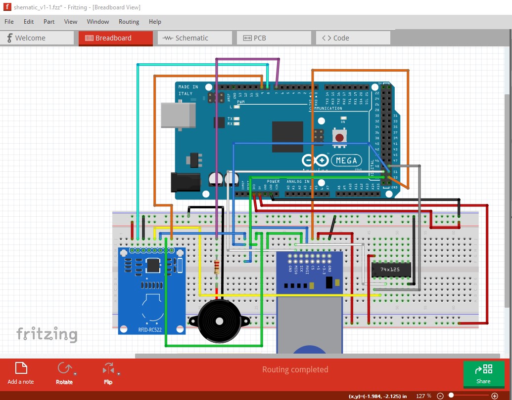
Here when the enable pin on the 74ahc125 is high the output it tristated so the SD card can drive the MISO pin. When the RFID wants to drive MISO, the enable on the 74ahc125 needs to be low to allow that.
This looks unwise. The mfrc522 data sheet here:
indicates the maximum input voltage is 3.6V feeding it 5V may damage the chip. As well later in the data sheet it indicates that
“[7] During typical circuit operation, the overall current is below 100 mA.”
so if the 3.3V supply will provide 150ma that should be fine.
Yes I don’t see any great problem with it.
Peter
Yes, but this is a much quicker and simpler workaround which works perfectly. I found it on the Arduino Forum.
But the resistor is dropping the voltage, so it shouldn’t be a problem.
Thanks again.
The resistor will only drop the voltage if there is current flowing, and how much it drops the voltage depends on how much current it is taking. When not transmitting that looks to be only around 10ma or so (with 100ma when it transmits I think.) The chip can be damaged with more than 3.6V applied to it, so you are safer to power it directly from the 3.3V supply. They said that reception distance drops with less than 3V supplied to VCC, but I doubt more voltage will help with range much if at all.
Peter
1 Like
Ok, I will keep that in mind. No more doubts. Thanks.