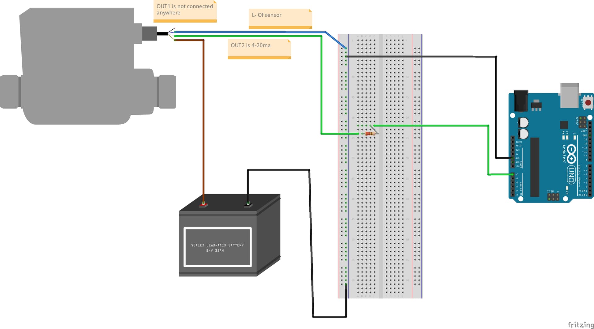
i am totally new in this field have no background of electrical or coding . i am attaching my project in which i am planning to connect SM6020 flowsensor to the arduino uno . flow sensor has 4 pin +,-,out1,out2 where out 2 is 4-20ma and about out1 not much idea. sensor is operated at 24 volt dc.
so in my circuit , i joint + of sensor to the + of power supply , - of power supply to the - rail of bread board . - of sensor to the - rail of bread board and - rail to the GND of Arduino uno so all sharing common ground . out2 which is 4-20 ma this is connected to one end of 220 ohm resistor and resistors second leg to the A0 pin of Arduino Uno.
note: out1 is i didnt connected anywhere.
could some one check , my connection are right or wrong . this will work in real ?. also can someone correct it . also please guide with code .
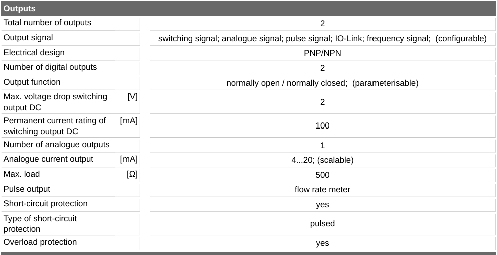
There doesn’t appear to be any information about connecting this to a Uno on the net so you are likely on your own. The data sheet has no particular information on output format. Your diagram has a few problems as well.There is currently no power to the Uno, so you either need to supply 7-12V to the VIN pin (which would require a regulator from the 24V battery) or via a wall wart or USB connection from an external source. Then you would need software to read the output from the sensor (the format of which is not clear from the data sheet) which you would need to write since there doesn’t appear to be anything available on the net.
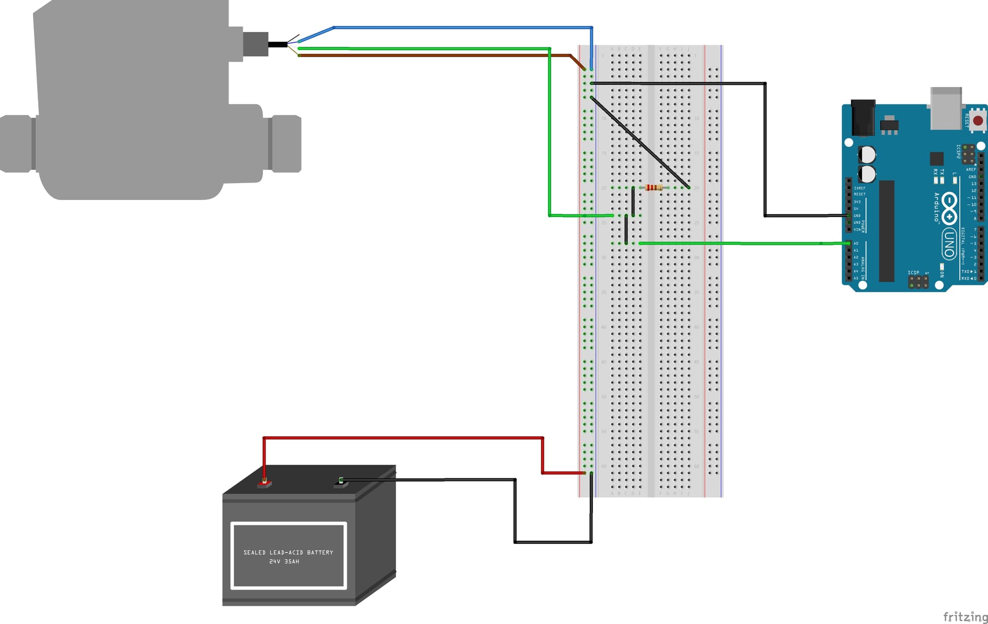
A0 pin through 220 ohm resistor . i am attaching my file . let me know about the connections and to the arduino i had not mentioned power supply . it will supply at end .
That should do what you want. The resistor should change the 4-20ma to a voltage which the Arduino will then read (with appropriate software. You would need to scale the output to relate to the flow rate I expect but other than that this should work (as long as the Arduino is powered some how.)
Assuming the Arduino is powered (either via the barrel jack, the USB port. or VIN via 7 to 12 V) then the 4 - 20ma input across 220ohms will produce .88V (4ma in) to 4.4V (20ma in) at the A0 input. That is in the range allowed for analog input on a 5V Uno so reading the analog value from port A0 will give you the value of the 4-20 ma input. Now you need to figure out how that relates to flow in the sensor and how you want to display or use the data in the arduino. As @RAPTOR7762 said the Arduino forums are likely the best place to get coding instructions although you will need to figure out what the numbers mean and what you need to do with them with information from the sensor vendor (either via the data sheet or their tech support) and what you need to do with the information (none of which we know.)