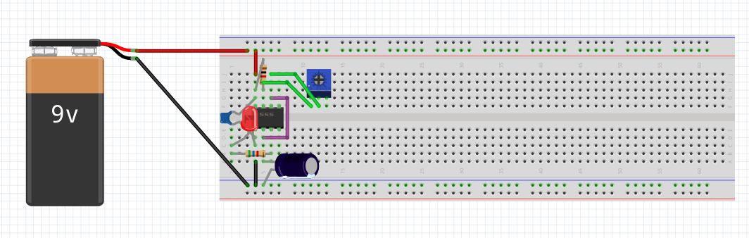
I hope this message find you well. I am new to fritzing and trying to make the knight rider circuit for which need to make astable 555 timer. but program outputs this error
The simulator gave an error when loading the netlist. Probably some SPICE field is wrong, please, check them.
If the parts are from the simulation bin, report the bug in GitHub.
Errors:
stdout Note: No compatibility mode selected!
stdout Circuit: simulator netlist
stderr Error on line 2 or its substitute:
stderr c1 0 3 100 n ic=0
stderr unknown parameter (n)
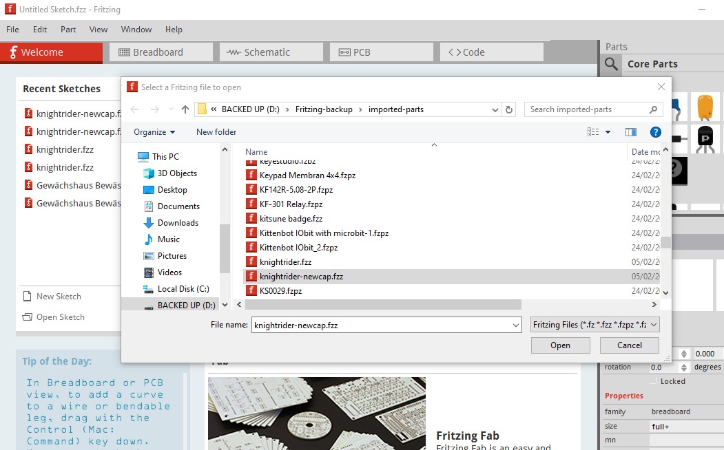
Your best bet is to upload the sketch (the .fzz file, upload is 7th icon from the left in the reply menu) so someone that can help (likely @fai) can give you an answer.
Yes, for me it just hangs Fritzing when simulated but the sketch loads correctly, I expect @fai (who wrote the simulator) will be the one to figure out what is wrong.
I do not have my computer not to test, but it seems that the problem is related to the capacitor (there is a space between 100 and n). Could you tell to replace the capacitor with a different one?
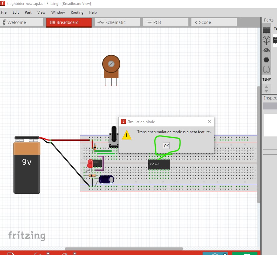
In addition, you need to run Fritzing in debug mode and use the transitory simulation. See other posts in the forum simulating a 555.
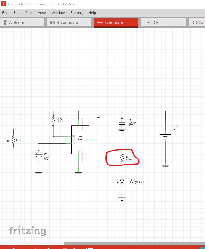
I think one problem is likely your resistor value on the LED is too high. As it stands at 9V it will only put about 1ma through the LED and LEDs typically need 10 to 20 ma to light, About a 1K resistor should get you to 10ma.
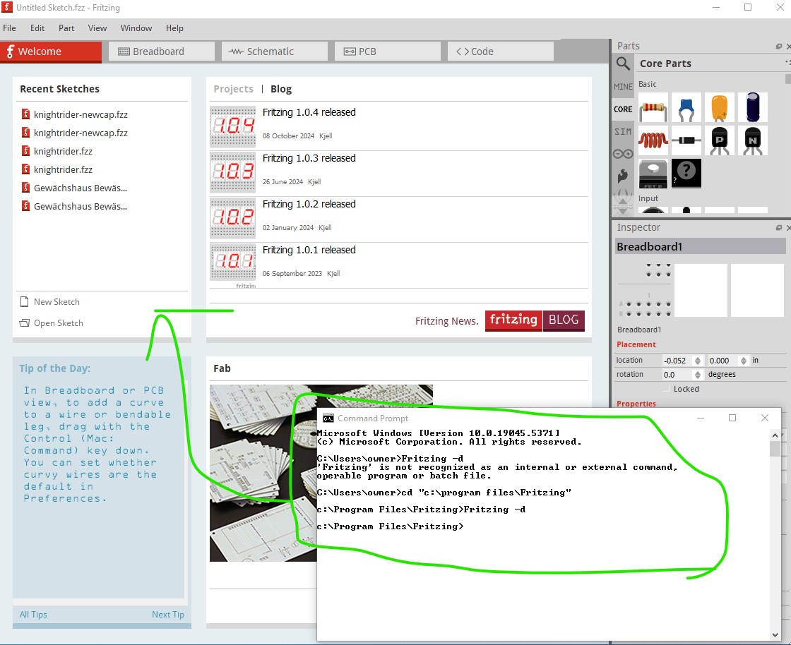
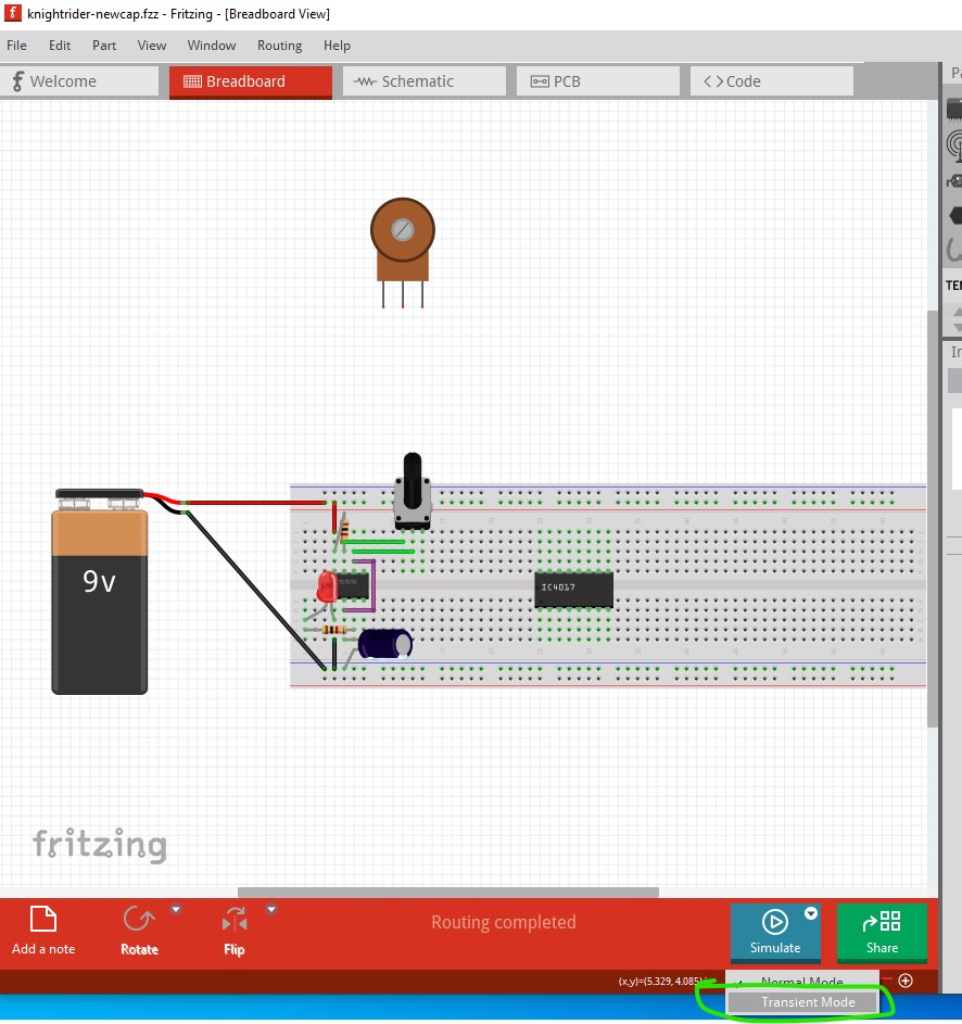
That said I still can’t get simulation to work even in debug mode with transient selected (you need to start Fritzing with the -d flag to enable debug mode then select the transient mode (greyed out here because debug isn’t active)
in order to get transient mode. Success, the problem isn’t the cap but rather the pot. Its spice model must be incorrect. Replacing it with the one from core parts makes this all work this sketch (run in transient mode under debug) blinks the LED as expected. Note I also reduced the resistor to 1K I don’t know whether 5k6 would work differently (the led may not get enough current to light I expect.)
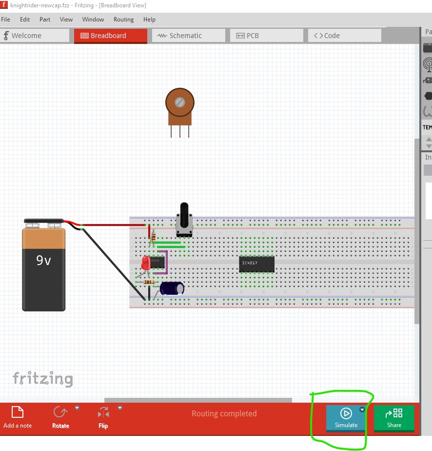
I don’t have a way to make a video (and couldn’t upload it any way) but if you try the sketch I uploaded with Fritzing in debug mode and select transient mode you should see the LED blink at a fairly fast rate for the 10 seconds of the simulation. When you get that working you may want to change the series resistor back to 5k6 and see if the simulation still works.
I don’t want to keep bothering you but can you please if you may share me how you get the transient mode working i don’t understand where the terminal is it the windows terminal or does fritzing software has one? please share the commands used thankyou
Durgesh
OK here is the sequence I used (my DOS window path setting is obviously broken so I had to change to the Fritzing directory to start Fritzing) Open a DOS command window (AKA the terminal) then launch Fritzing with the -d flag (there probably is a way to specify the .fzz file too but I was too lazy to find it.) That will launch Fritzing:
I had a look at the original file. There were two errors as @vanepp reported.
The first one in the capacitor C1. There is a space between 100 and n (“100 n”). That space confuses ngspice. But I am not sure how you managed to do that. I tried to add the space in a capacitor using the inspector and adding spaces is not allowed there.
The second issue is that potentiometer. The spice field seems ok, but that part needs two extra properties: the “knob status” a “max resistance”. Check other potentiomenters. I could not find that pot in the core parts. Let me know if it is a part that comes with Fritzing. If so, I will fix it.