I’m working on a custom PCB that will be used with silicone elastomer button pads—like the ones that have a conductive rubber or carbon pill underneath. I know Adafruit provides an EagleCAD library with proper footprints for these kinds of buttons.
However, I’m wondering if there’s an easy way to do something similar in Fritzing. What I mostly need is a way to create the typical circular (or interleaved semicircle) contact pads.
Has anyone successfully done this in Fritzing? Is there a custom part or footprint available?
Any tips or examples would be greatly appreciated!
Ah! For whatever reason, that part didn’t get translated by Eagle to Fritzing. It does appear in the board file (probably doesn’t show up as connectors in Fritzing and was thus ignored.)
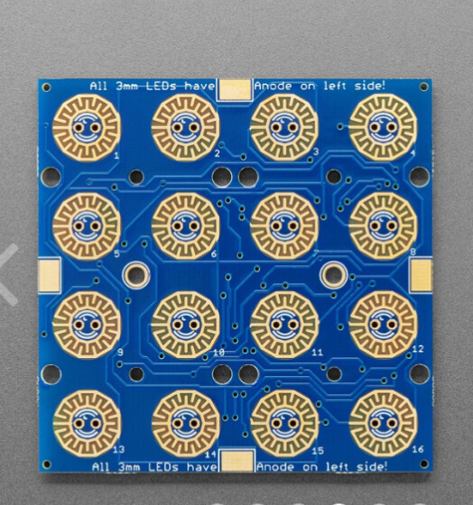
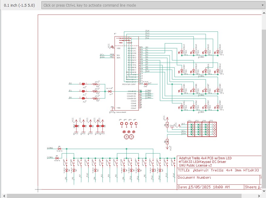
but didn’t translate to pcb. From the schematic there appears to be a lot missing, they appear to be using a keyboard decoder to drive the LEDs and deal with the keys which isn’t showing. That makes how the keys are supposed to connect unclear (there are also a bunch of diodes apparently missing.)
although that doesn’t appear in the brd file. It appears the brd file may only be for the board for the key interface, but then it is unclear how you are supposed to connect to it. So basically the answer is it is possible (if not easy) to do this in Fritzing, but has not so far been done. The Adafruit eagle libraries are probably not that useful.
I think this part should do what you want. It implements a single key (so to make a 4z4 keypad you would need 16 of them with a variety of extra holes.) It is an odd part in that it mixes through hole and SMD (the connectors for the switch are only on the top layer.) Note although you can connect the LED pads on the top layer they will short with the switch pads (and DRC will complain) so you need to route the LED connections on the bottom layer.
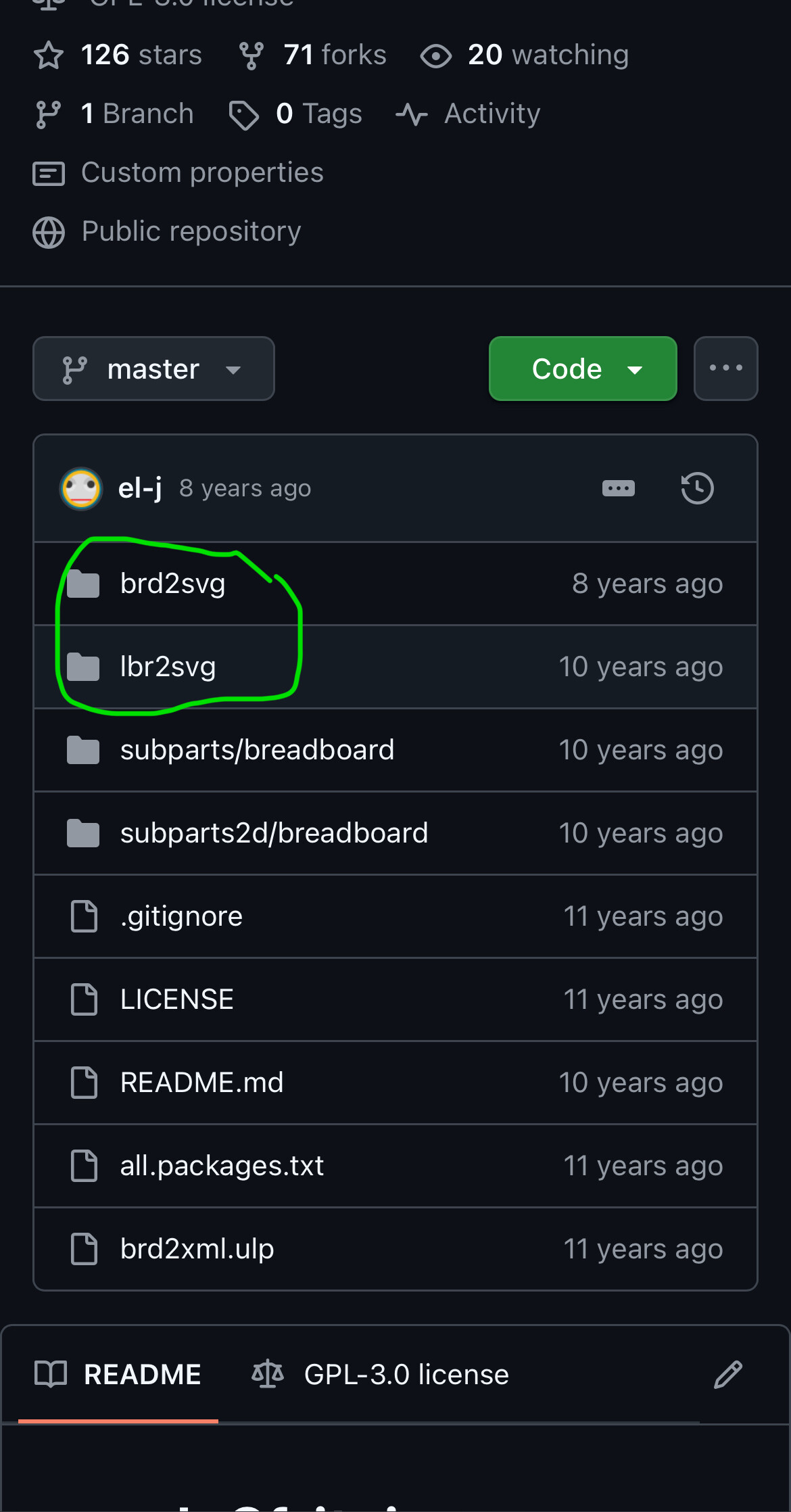
to do that you would need to use this pcb svg from the adafruit part to set the holes correctly
(right click on the image and select save image as to download the svg.) The various black circles need to be replace with the pcb hole part from core parts (and the hole size set correctly.) This svg should be the correct positioning for that Adafruit keypad.
Yes, indeed. My question was rather aiming at the eagle 3-6 format, which was binary and most software does not read it. From eagle v7 on it was an XML based file format which readily is converted by many software suites.
I found this out the hard way when I happily had found a part, I was looking for, as eagle file and then just been able to achieve an error message that the file format is not recognised.
Eagle2fritzing is only xml I believe although there is something in there that may convert previous versions. If you have an old format file I have a copy of Eagle2Fritizing and can see what it produces. It is also easy enough to make a part without Eagle2Friting (assuming you know how to make parts) from a web site with physical dimensions and connection information (and preferably a flat picture for component placement in breadboard.)