That worked, don’t know what happened with the first one. Looks good and would work as is, but I would increase your clearance in places because you have the room to do so. This is the copper bottom layer of the above fzz from gerbv:
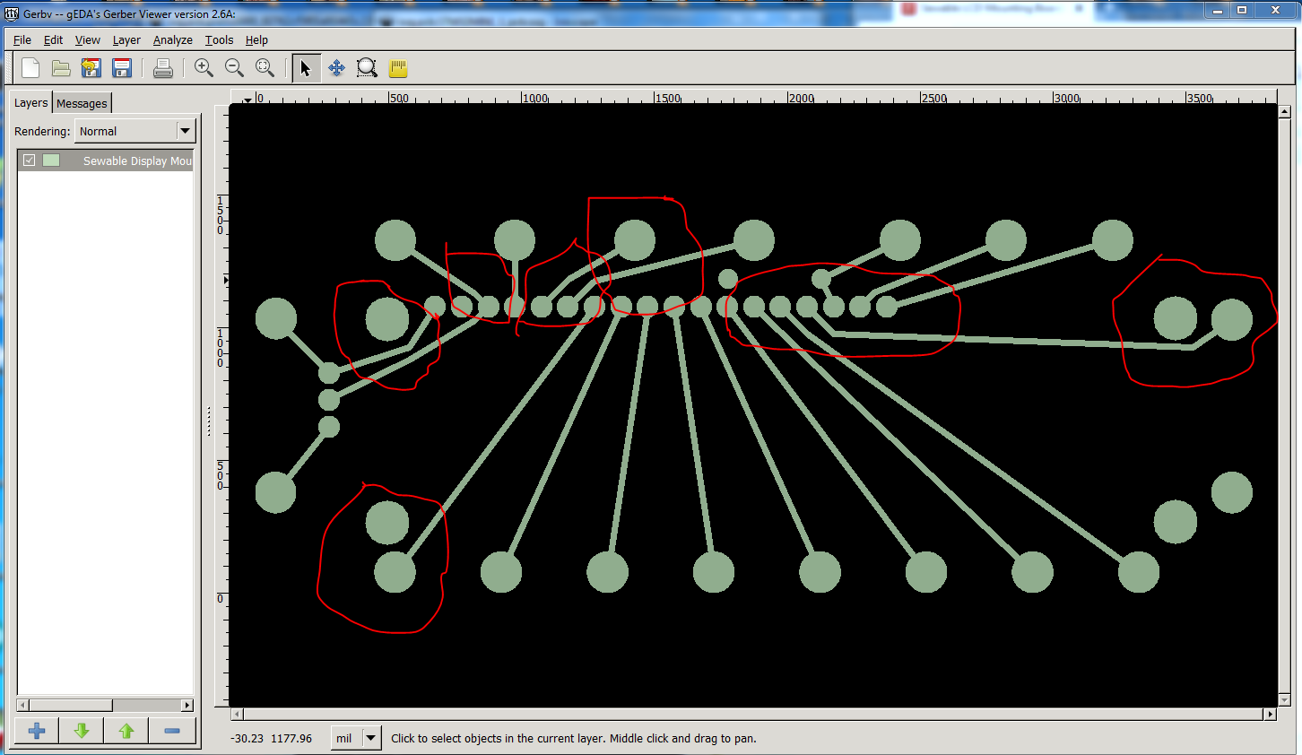
The red markers are places where I would reroute for more clearance. If possible (I didn’t do it here) I would move the sew pad by the bottom left mounting hole to provide more clearance for the mounting screw. Here is how I would route this:
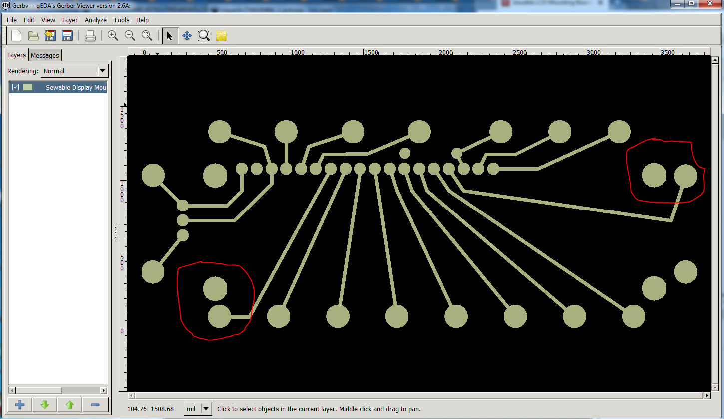
again the sew pad I would move if possible is circled in red. Now the same with the top (less changes there):
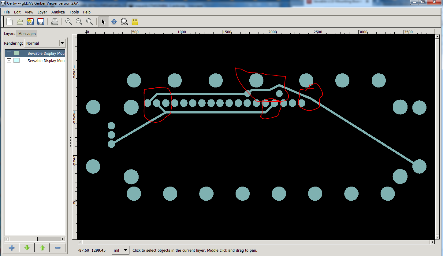
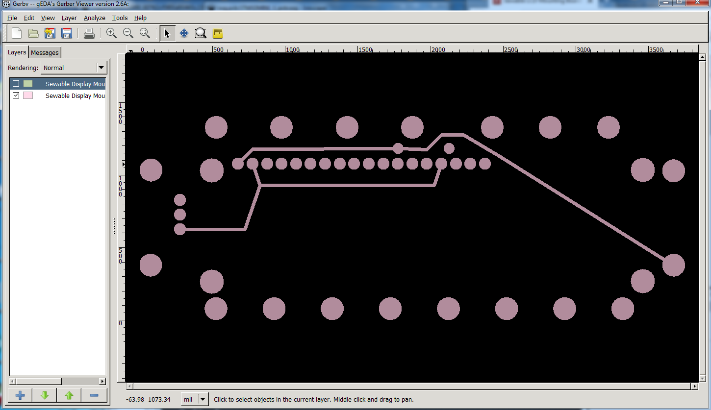
and how I would do it:
Now the complete board with bottom , top, drill and silkscreen top layers which is how the board will actually look (this is the one with my changes):
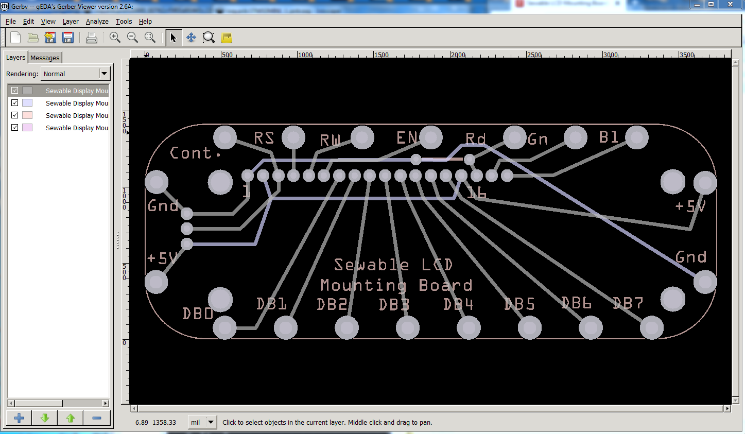
and the fzz that produced this:
edit: I see I missed one trace, so I corrected that and replaced this fzz, the circled trace in the top left is changed in this fzz to provide more clearance.
Sewable Display Mount PCB-4.fzz (12.4 KB)
Peter