When using schematic view, how to join wire bendpoints together? All same ground wire source. Some bendpoints have auto-joined.
Using Version 0.9.4
While I’m not sure I understand the question, uploading a copy of the sketch (the .fzz file, upload is 7th icon from the left in the reply menu) is a better bet, here is an attempt at an answer. Here I am assuming you are trying to connect the 3 IC pin 4s to ground:
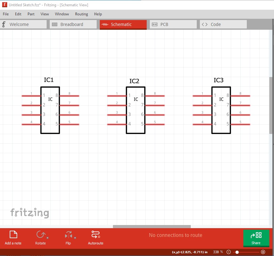
You need to always connect from a pin to a pin until the connection turns green (from red) on both ends:
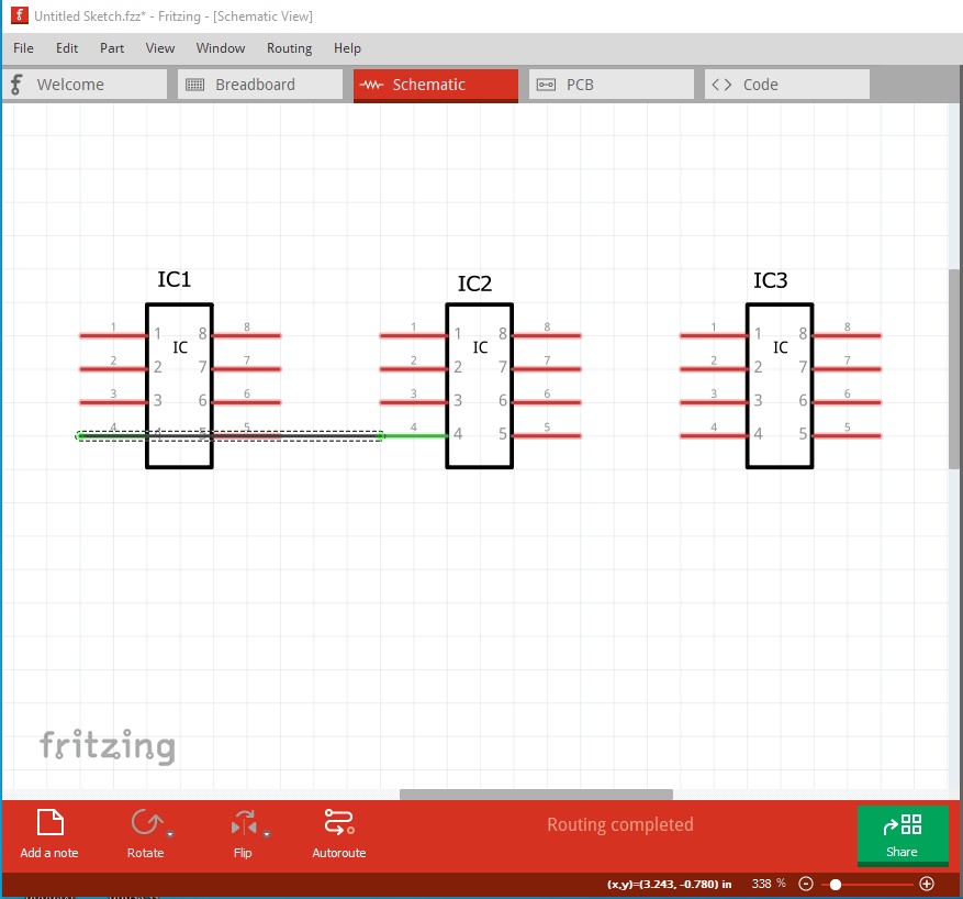
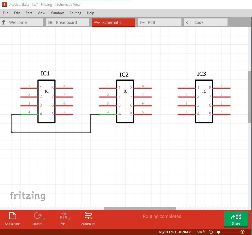
once the connection is made, then click and drag the wire to create the bend points:
now connect IC2 pin 4 to IC3 pin 4 same as 1 to 2:
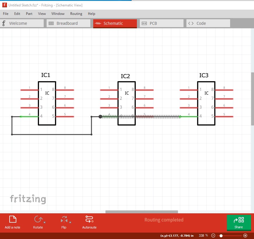
and click and drag to make the bend points:
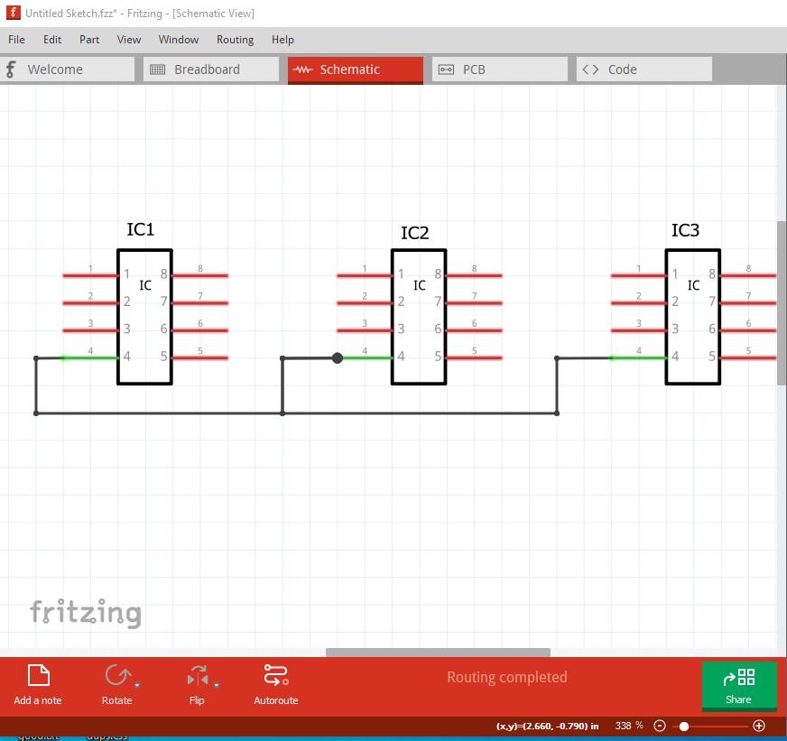
What is really happening is this (but arranging as above is neater!):

That said, a better way to do this for power or ground is via one of the predefined nets (ground in this case) like this:

Here I dragged the ground symbol for schematic from core parts (the red circle and arrow on the right) in to the sketch and connected two of them. The third needs the same treatment: connect a wire from the ground symbol to pin 4 and they are all connected to the ground net. Click on any one of the pins and all the rest will light up yellow to indicate they are connected. If this didn’t answer your connection then as noted a sketch indicating the problem would be a better bet.
Peter