It sounds like you are using parts editor (which I usually don’t as it is incomplete.) If you set the pins from there you can automatically set terminalId from here:
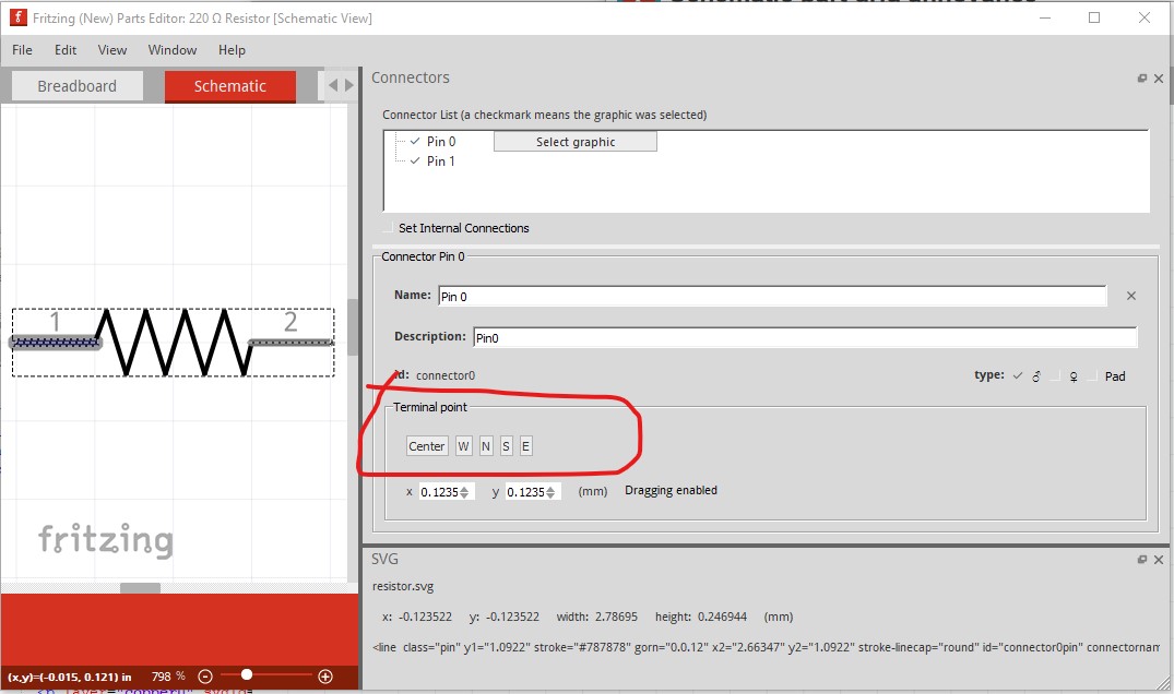
In this case I would want to use W (for west) I believe (although I have rarely been able to make this work, which is another reason I don’t use parts editor!) The default without a terminalId as noted is Center which is about the 1 in the middle of the line. There is a dangerous omission in my post, as well as the terminalId in the schematic svg you need a corresponding definition in the .fzp file associated with the part, if both are not present the terminalId won’t be recognized. In the fzp file this is correct:
     <schematicView>
      <p layer="schematic" svgId="connector0pin" terminalId="connector0terminal"/>
    </schematicView>
but this will exhibit the same problem (because the terminalId won’t be recognized):
    <schematicView>
      <p layer="schematic" svgId="connector0pin"/>
    </schematicView>
I don’t use parts editor enough to give a good answer to this, but it sounds like the pin hasn’t been defined (my usual problem!) correctly because the connector selection didn’t work. In such a case the wire will connect to the center of the part (usually with a red square indicating a connector definition problem) in the the views because Fritzing didn’t find a connector definition for a connector that is in the fzp file and uses the center of the part as the end point for the wire.
While I’m not entirely sure what this is, the last thing you should do after editing an svg in Inkscape is Edit->Select All then Edit->Resize page to selection. This sets the bounding box (which Fritzing uses to define the outline of the part) and the viewbox to match the image.Another common problem is having the units set to px like this:
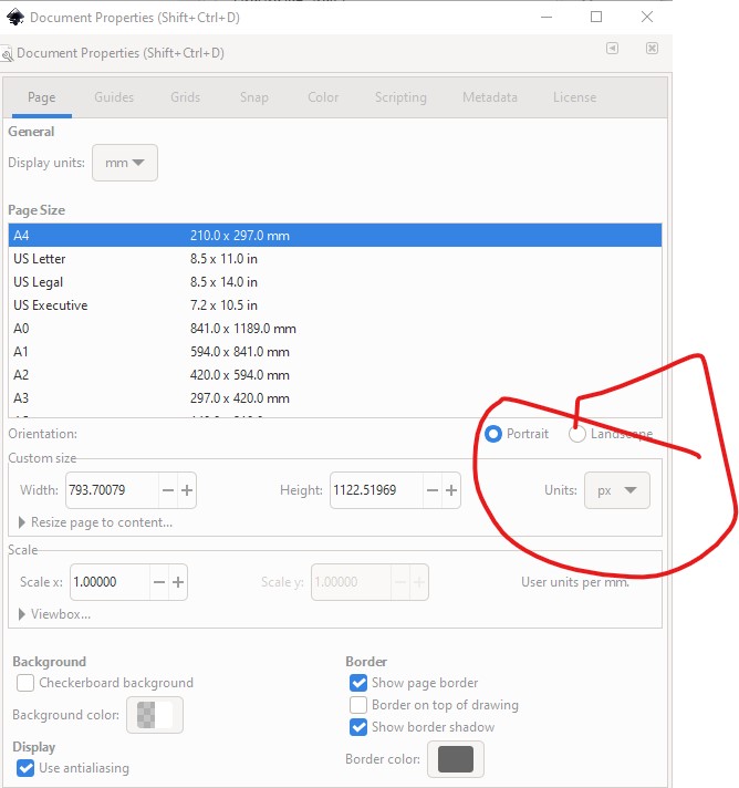
in Document Properties. Fritzing will then guess what the DPI value for px was (72DPI for older Illustrator, 90DPI for early Inkscape) when current Inkscape is 96DPI and then there are scaling problems in Fritzing (parts come out at the wrong scale and fail to align to the grid.) Setting the units to in or mm fixes this since an in is always an in like this:

Fritzing needs to know the size of the parts in real world units so the pcb gerber output can be in inches, which is the base of the reason Fritzing needs dimensions set in the svgs.
Peter