Hello everyone, I am still new to fritzing; I have a problem with my schematic diagram; it stated that there are 0 of 4 nets routed - 4 connections still to be connected. I don’t understand this, as my breadboard diagram shows that all has been completely routed.
Can someone help me with this?
설계도.fzz (10.8 KB)
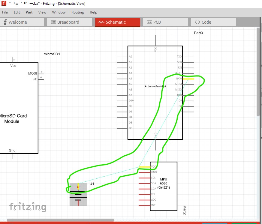
In schematic
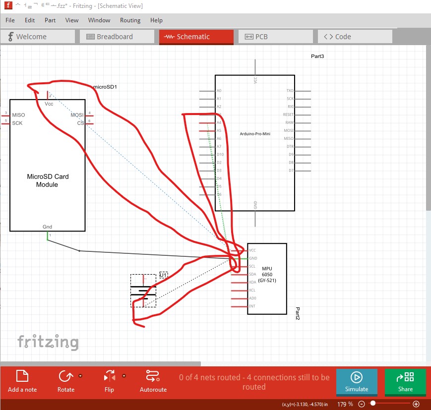
The 4 unrouted connections are indicated by the rats nest lines (the colored dotted connections) and need to be clicked on and routed to work like this:
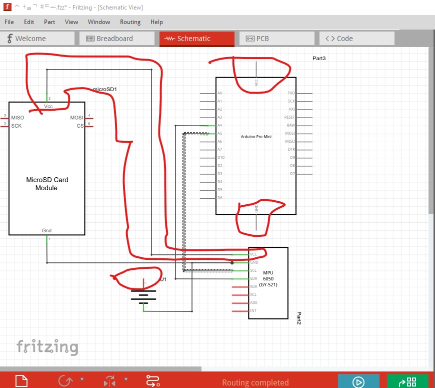
With that done routing is complete but incorrect as there is no power connection to one side of the battery and no power at all to the pro mini so this won’t work even though routing is complete. You need to make the appropriate connections in breadboard before schematic will complete correctly. It is best practice to complete breadboard (or schematic or pcb) first and then click on and route the rats nest lines in the other two views to complete the sketch. Making an incorrect connection in schematic or pcb will reflect back in to the other 2 views and can cause problems.
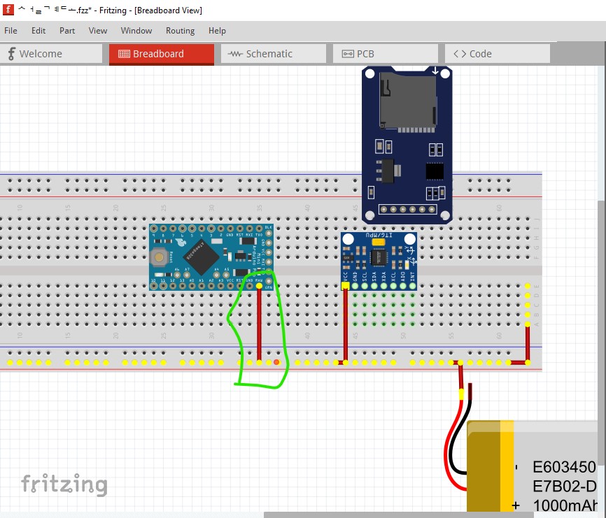
Clicking on a pin any view (breadboard here) lights all connected pins yellow like this:
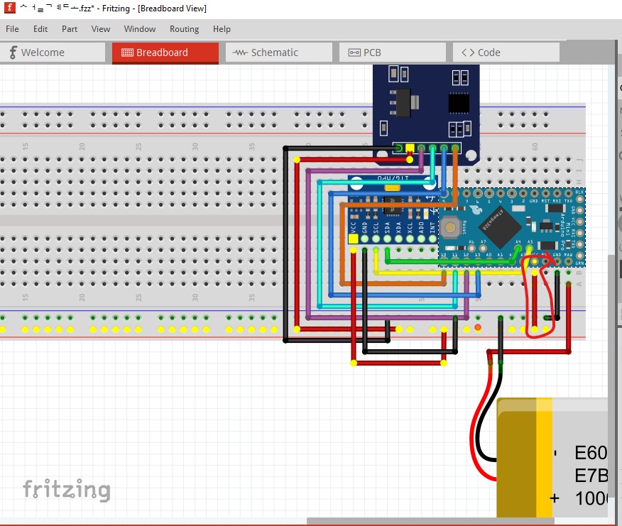
which indicates you should have connections to ground and +5V on the pro mini but they are not showing up in schematic. I would suggest deleting all connections in all views and redo breadboard and see if that corrects the problems. There appears to be a problem with the pro mini part as the raw pin isn’t connecting to the breadboard correctly.

While this appears correct, switching to schematic indicates it is not as there is no rats nest line (indicating a connection) there.
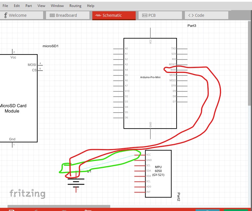
Moving the wire to connect directly to the pin on the pro mini makes the connection:
then the correct rats nest line appears in schematic.
That is probably your easiest workaround for this issue. Hope this helps.
edit:
Some more poking indicates I fixed this at some point in the past (but haven’t yet submitted the update.) At this point I don’t remember what the problem is exactly but this part (with a change to grid size) should do what you want.
Arduino Pro Mini (3.3V)-fixed.fzpz (16.8 KB)
Sometimes it picks one of the end pins as the reference which mis aligns the pins with the breadboard
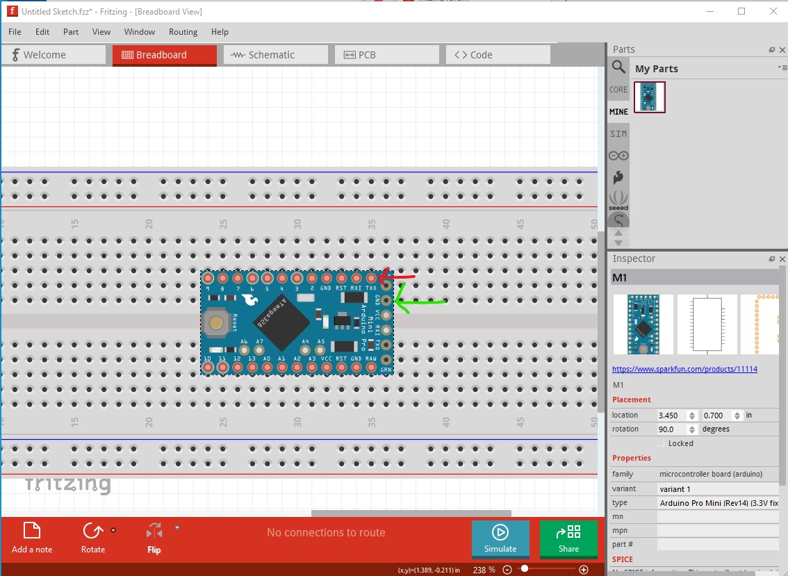
here the edge pin is aligned to the breadboard which makes the top and bottom pins not align to the breadboard. To fix that you need to change the grid size to 0.05in
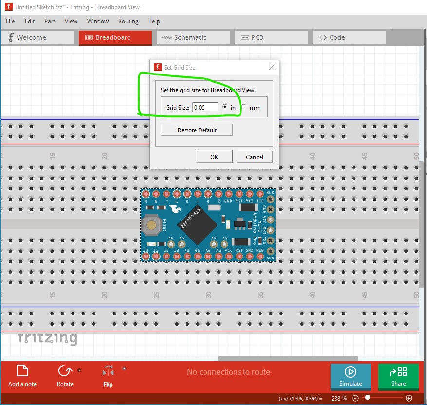
then move the board until the top and bottom pins align to the breadboard like this
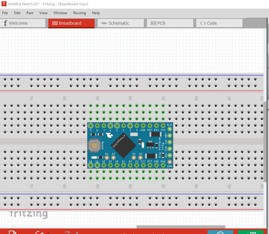
Now the pins connect to the breadboard (note the breadboard pins on top and bottom are green indicating they are connected to the mini) and all should be well.
Peter
1 Like