I am building a TR-808 Kick clone from the schematics provided by the service notes and adapted by Eric Archer on his site .
The schematic doesn’t fit on one breadboard easily so I am trying to make it on two breadboards.
As I am new to electronics I have several questions specific to Frizzing :
I am not sure where the power lines + /ground should be connected, the circuit wants 15VDC but I don’t see it in the schematic, I only see a symbol like ( + ) +15V , which I assume means connect this leg of the component to the positive power rail (red power line) on the breadboard - is this right?
There are numerous (GND) ground areas, are these to be connected directly to the negative (blue) power line on the breadboard. What I noticed is that these can either be connected to each other where the rats nest is defined or if I connected to the blue line on the breadboard. This seems to do the same thing since the “routed” number decrements by one.
In Fritzing, the ratsnest lines, they often appear across a resistor, does this indicate that I need to put a pumper across the resistor pins?
Is each color rats nest line a different trace - analogous to what is on the PCB that is in the PDF (GRND, PWR, TRACE1, TRACE2)?
In Fritzing, the rats nest wires will jump around from one component to another if i move the component, is this basically Fritzing trying to find the easiest way to route the connection?
It appears to want (but doesn’t show the source of) +15V, and -15V both referenced to ground. For your real circuit a couple of regulated 15V wall warts (one connected normally, the -15v one with the +15v wire connected to ground and the ground connection of the wall wart connected as -15v). There are other options available as well (such as a single 48V non regulated wall wart and 7815 and 7915 regulators to get the needed ±15 supplies) if you tell us what is important, such as size, cost, only one connection to the power line (the suggested solution needs 2 sockets which may not be acceptable) or something else. You are correct that the +15V supply will go to one power rail, ground to another power rail and -15V to a third power rail or you can just jumper the various pins that need power to each other (although using the busses is usually easier) any of those should work.
Correct a connection is a connection either via the ground bus or by direct wire between pins. Note that the rats nest lines take the shortest (not always best) direct route between pins.
As noted above the rats nest line is the shortest route between pins, it ignores things like resistors. What may be easiest is to click on the rats nest line then drag the resulting wire away from the direct route. That should show you exactly where the end points are. One potential difficulty is that if you click on a part of the rats nest that is over a connector you may accidentally make an unintended connection, so its best to check the schematic to make sure it agrees there should be a connection there. As well you are welcome to post your sketch .fzz file via the upload butting (7th from the left on the reply tool bar) and we can have a look at your sketch and provide advise and/or corrections. In general a rats nest line that appears to short a resistor is probably either an error or just passing over the resistor to a different connection (which creating and moving the wire should show).
Each ratsnest line is a different net which is the collection of all pins that should be connected together, so yes that will turn in to a trace in PCB view to connect all the pins together.
It is likely more the graphic program finding a “closer” (for its idea of close) route to get between the two connected points.
What size? 1/4 inch or one of the 3.5 mm types. There doesn’t look to be one in core parts but I think there is one for at least the 1/4" type jacks available on the net (someone else is working on a midi project and needed 1/4" mono). If you get the size, a google search with a search term like “fritzing part mono jack” may turn up something. One last note about a Fritzing bug: it is best to make all your connections in one view (sounds like schematic would be it in this case) and then use the rats nest lines to route the other two views. If you make changes in more than one view the parts database sometimes gets corrupted and you get rats nest lines that shouldn’t be there. The only solution to that is to start again which can be painful (which makes it a good idea to keep a copy of the project when it is complete in one view so you can at least restart there if you have to).
Unfortunatly you look to have hit the fritzing bug and corrupted the parts database for this sketch. That is likely because of the connections made in pcb view and/or some wiring errors in breadboard view. The only known solution is to start again. Here are some of the things I see wrong and suggested solutions:
your op amp problem is because you aren’t using an op amp with sub parts. I thought the generic dual op amp had sub parts but that doesn’t appear to be correct. However the ADTL082 in core parts (which you can find by entering ADTL082 in the search field and hitting enter) does and has the same pin out as the tl072. What that means is that because of the sub parts you can move one section of the op amp around independent of the other in schematic as you want to to make the schematic identical to the original.
You need two power supplies, but have only used one in breadboard. That also has bearing on your battery question. While the schematic calls for +/-15V in practice the op amp will take anywhere between +/-5V and +/-18V. If you want to run off batteries (as opposed to a line operated power supply) and possibly even off a line operated supply such as a wall wart one of these is a good bet:
It is possible that the device that is supplying the trigger signal may also be able to supply 5V which would fix your power problems, if not there are some other suggestions below. This device takes 5V in (you still need to get regulated 5V either from the device providing the trigger, a regulated wall wart or from a 9V battery and a 7805 type regulator) but it will give you the +/- supply voltages (at 12V rather than 15V) that you need (the original schematic indicates that either ±/15 or ±12 is fine). The above is less than $2 with free shipping (but it takes a long time to come!). Another possibility is 2 9V batteries connected in series to give you +/-9V. Transistor bias resistors may need some tweaking or may not (I’d say try it as is first and see if it works ). On the breadboard I’d use the top two rails for +15V and gnd and the lower 2 one for ground and the other for -15v and repeat that setup on the bottom breadboard and do the interconnections as you have but with 3 wires rathar than 2 as at present. You should first do the complete schematic and then save a copy of it as an fzz file in case of later problems so you can go back to that rather than start again as is probably needed this time. Complete all the connections in schematic first and then move on to breadboard (keep a copy of the current fzz file so you can copy the layout of the current breadboard when placing the components as that seems mostly fine) and then click on a rats nest line to create the wire and drag the resulting wire in to a neat route (I like to use straight lines and 90 degree bends but whatever works for you). You probably want a second phone jack to connect to the trigger input (and I think the current phone jack is connected wrong, in schematic it is connected to the output, in breadboard it is connected to the trigger input which will cause problems in the database as it shorts the trigger input to the output). Since you only need mono you may want to use the RCA jack instead (probably the third one which has a correct mono schematic). You may want to first post you finished schematic fzz and let us look it over and see if there are any problems before trying to make the breadboard. Don’t make any connections in pcb (as they will reflect back in to the other two views and cause problems if they aren’t correct!)
Edit: Here is how I would do your schematic (you should check to make sure I got it all correct though ). The main changes are the addition of a 3 pin .1 inch connector for power (when I find my ±12V power supply boards I will make and upload a part for them and add that in to this as the power source). I used RCA connectors for the trigger and output connectors (you can switch back to the phone jacks if thats what you need or 2 pin .1 connectors like the power one, what ever suits you) and I used the TL082 op amp with sub parts so I can move each half of the op amp to the appropriate place in schematic.In breadboard I rotated both breadboards by 180 degrees to put the red power strip at the top. The top red strip on each breadboard is +12V all the blue strips are ground and the red strip on the bottom of each breadboard is -12V. Appropriate (and appropriately colored) jumpers connect them altogether and to the pins on the power connector. Besides that I moved all the components (which start out stacked on top of each other) so that they are all separate ready to be placed on the breadboard. When doing this if you create a wire by clicking on a rats nest line by accident (which I do often), select the wire, right click and click delete wire to remove it again leaving only the rats nest lines. From here you can then place each component where it should go on the breadboards (using your original layout would be fine). Then click on one rats nest at a time and pull the created wire in to an appropriate position, preferably not overlapping any others and at 90 degree bends. That should end you up with a working circuit and none of the odd rats nest lines in your original.
Thank you Peter. I started to modify the original using the IC you provided. I didn’t start from a blank breadboard, I copy and pasted the schematic so as to preserve the design. I deleted the breadboard so I can see the rats nest cables unhindered.
After having done this I still see a huge number of rats nest lines. Is this the bug you mentioned?
How did you create this file you uploaded? Did you use the existing components or did you have to recreate the schematic from a blank project in order for the file not to be corrupted?
Thank you for all your help, I hope to soon have a booming Bass Kick and that this will help others trying to learn percussion synthesis.
I indeed had to start from a new sketch and redo the entire schematic. Once the data base gets corrupted we don’t know of a way to correct it. Even deleting all the lines in all three views isn’t enough to fix it. I think the routing code is making some changes that it then doesn’t know it should undo again (which is likely a bug) but I’m not really sure. The only known working solution is to start again from scratch.
It seams like a lot of work redoing the whole thing, but it’s only the first one that takes a lot of time. Copying is very quick when you have both open at the same time, and a lot faster than trying to figure out something that might not be fixable.
I finally downloaded the file, you created and had a look. Thank you for clarifying what the power hookups are supposed to look like and the difference between the +12V, GND and -12V.
I relabeled the components and started to move components around in the breadboard view and what I noticed was that there are still rats nest lines that appear across resistors regardless of how I orient them. When I deleted these rats nest lines, it deleted traces from the schematic…so that now the schematic appears with un-routed nets.
Is the deletion of the rats nest lines an issue? Does a RNL across a resistor mean that I have to put a jumper across the resistor? I have spent a lot of time on this. Is Fritzing in fact able to model analog circuitry?
On that pic you haven’t put the wires in yet, so the ratsnests will still be visible. Only when things are connected do the ratsnests disappear.
The usual mistake is that you are probably not trusting the ratsnest, and are connecting parts differently from the SCH. The SCH is the master, so you have to trust the ratsnests in other views.
I do circuits with 150 parts and never have problems, that one only has 50, it just takes practice.
I understand that the rats-nest lines disappear when the components are connected via wires, but why would the algorithm show a rats-nest across the three pins of the transistor above ?
Do I have to connect the components to their respective +12V, GND, -12V rails as I add them so that these “false/confused” rats-nest lines disappear?
I observed that when I click a breadboard “hole” that is highlighted in green, it does seem to be “aware” of the power lines since the entire power line lights up in yellow “dots”. The issue is however, that almost any component seems to want to connect to a power rail, only a very few components want to connect to a pin isolated from +12V, GND or -12V, this was the original issue I had, it seemed like the only way to get rid of the rats nest line was to connect the components to one of the V rails, so I ended up with a lot of jumper cables on my breadboard, some even for connecting adjacent pins on a transistor.
I noticed one thing though: for one or two components, when I click the green hole connected to a component, BOTH the GRND and -12V light up: does this mean I can connect that hole with a wire to either GND or -12V?
No it shouldn’t be across three pins of the transistor.
No, there is some fault.
The green dots are an indication that it is connected. Big black dots in SCH are junctions, but be sure to grab the dot and move it to see if traces are actually connected.
NO, one pin of a part should not light up both 12V+, 12V-, and GND.
I don’t know how VAN did that .fzz, because it seams to be a modified original.
If you want to upload VAN’s .fzz that you are playing with I can try and see what’s wrong.
Here is a big .fzz that you can play with to see how it’s supposed to work.
I had a play with VAN’s before and it looks fine. If you look at the parts he set out in BB view there is no rats between component pins, so it looks like something about when you put them on the BB.
When I see links between pins on a part and I can’t clear them, it looks like that part has corrupt associations that can’t be undone. Sometimes you can delete the part and replace it with a fresh one from CORE, but I couldn’t do that with your orig .fzz.
The way to do it is only work in one view until it’s perfect - SCH for you because you have it -, and then trust the rats in the others. Remember, it has to be perfect with every connecting verified.
EDIT
Grab the rats and pull it to see where it’s coming from. Sometimes they look connected when they are just running parallel.
It appears our usual advise that you can’t recover a corrupted sketch is incorrect. I just started with your original sketch and deleted all the wires in all the views (including the breadboards, because they create virtual wires when things are connected to them). That eliminated all the rats nest wires (which we didn’t think could be done). It wasn’t easy, as there were several wires that were very hard to see, I ended up using autoroute in pcb to create a wire so I could see what component had a connection, and then discovered a close to invisible wire in breadboard that I had missed! That sketch is here:
Then using the above sketch I added the two breadboards back in from core parts, and unlocked all the components and moved them so that they connected to the breadboards. That creates this sketch which has some problems already:
The only change on this one is that the 2 breadboards have been added back in and the components unlocked and moved so they connect on the breadboard. If we now switch to schematic and look at the rats nest lines the connections create we see why the problems occur in the original. Some of the rats nest lines match the wires on the original schematic, but some do not. For instance if we look at the base of transistor t5 on the left, we see the rats nest line from breadboard is connecting to the bottom of resistor R20. In the original schematic there is a connection from the bottom of R20 to the ground just below it. That however if done, will create a short between the base of T5 and ground. To correct that R20 in schematic needs to be rotated 180 degrees so the currently unconnected pin of R20 points towards ground, so when the connection to ground in schematic is made it will match the connections already made in breadboard rather than cause a short as it will now. R33 on the emitter of T5 should be eliminated and replaced with a wire (I did that on the schematic I made). One end of R21 is connected (in breadboard) to the ground end of D2, with a connection to ground on the cathode of D2 there will be a short on one end of R21 that shouldn’t be there. This indicates there is a placement / connection error in breadboard view that needs to be corrected. C9 connects to the anode of D2 in breadboard (which it shouldn’t) again indicating there is a connection error in breadboard view that needs correcting. Similarly the base of T2 connects to the emitter of T4 which should connect to ground in the schematic and which will cause a short. That needs to be corrected in the breadboard layout by moving the components so they don’t connect incorrectly. You need to go through the rest of the connections and move the components in breadboard until the rats nest connections in schematic match correctly (or start with the competed schematic and make sure the two views match. Starting from here should let you use most of the original layout in breadboard (once you correct the parts that have problems either in schematic or in breadboard which ever is easier). Note you probably want to replace the current op amp with the tl082 to get the sub parts to be able to move them around as well.
edit: as promised, I just uploaded a part for the ±12V converter I mentioned above to parts submit in thread:
While making it I discovered the input voltage range is actually 2.5 to 5.5V so it will run off 2 AA cells if you want your device to be battery powered.
Thanks Peter! Using your initial schematic, I laid out the breadboard. I think I understand the issue better now. The underlying issue with my assumption that the schematic view and that the breadboard view understand non-polar components such as resistors or non-electrolytic capacitors.
The main issue with my prior board that was causing all the addition odd ratsnest lines is that I often rotated resistors as I would normally BUT Fritzing is very strict about the pin numbers so flipping a resistor or capacitor causes the schematic to put a ratsnest line across the resistor because it wants the original “pin” orientation to be correct exactly like the schematic.
Once I followed the schematic and laid the components in the strict way “pin wise”, the schematic view stayed intact with “routing complete”.
These were excellent instructions and help, I am confident these changes along with the additional part you created will bring this project to life.
Yes that is one of the limitations (as well as the strength) of changes in one view reflecting in to the others. It isn’t necessarily obvious that orientation matters between views on non polarized components. Sounds like you have it straightened out though and that is good!
Not exactly, it will only provide one half of what you need. There are a variety of ways to do this, two 12V Wall adapters will work (one to provide +12V and the other to provide -12V) it needs 2 power sockets (which may not be an issue). That may be the easiest and it should work. One of the adapters provides +12V and the other has its +12V lead attached to ground and its ground lead connects to the -12V lead on your breadboard (providing -12V relative to ground). Another option is a regulated 12V wall adapter and a boost regulator module that will take 12V input and produce a 24V regulated output. Ground for the boost module connects to +12V and the 24V output provide the -12V output. This unit from pololu will do it but is quite
expensive at $11US,
an similar unit from ebay is $1 US (but long delivery) such as this one:
In either case you would need to adjust the supply output to be 24 V (as both boost modules are variable voltage). A 5V wall adapter and one of the ebay modules I referenced earlier will work as well with no voltage adjustment required (as the module takes 2.5 to 5V in and outputs ±12V already), the 5V adapter (or 2 AA batteries at 3V) will power the module and it will produce the needed + and - 12V to power your circuit. The downside to it is shipping from China for the module can take up to a month or so via mail, so it isn’t necessarily fast if you are in a hurry and as the module is only $2US overnight delivery would be probably expensive. You could also make a split power supply from a 24 volt center tapped transformer, rectifier, capacitors and 7812/7912 regulators (there are instructions on google for doing so), but you don’t seem to be able to buy a cheap +/-12V wall wart from any supplier I can find. You used to be able to find them surplus sometimes, but even my favorite surplus suppliers don’t have any.
 ). On the breadboard I’d use the top two rails for +15V and gnd and the lower 2 one for ground and the other for -15v and repeat that setup on the bottom breadboard and do the interconnections as you have but with 3 wires rathar than 2 as at present. You should first do the complete schematic and then save a copy of it as an fzz file in case of later problems so you can go back to that rather than start again as is probably needed this time. Complete all the connections in schematic first and then move on to breadboard (keep a copy of the current fzz file so you can copy the layout of the current breadboard when placing the components as that seems mostly fine) and then click on a rats nest line to create the wire and drag the resulting wire in to a neat route (I like to use straight lines and 90 degree bends but whatever works for you). You probably want a second phone jack to connect to the trigger input (and I think the current phone jack is connected wrong, in schematic it is connected to the output, in breadboard it is connected to the trigger input which will cause problems in the database as it shorts the trigger input to the output). Since you only need mono you may want to use the RCA jack instead (probably the third one which has a correct mono schematic). You may want to first post you finished schematic fzz and let us look it over and see if there are any problems before trying to make the breadboard. Don’t make any connections in pcb (as they will reflect back in to the other two views and cause problems if they aren’t correct!)
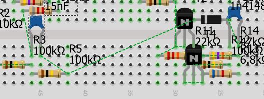
