Thanks for the detailed answer.
The english page indeed contains a typo. The free text description is wrong (a missing trailing 0), the technical specs are correct (align with the linked PDF datasheet).
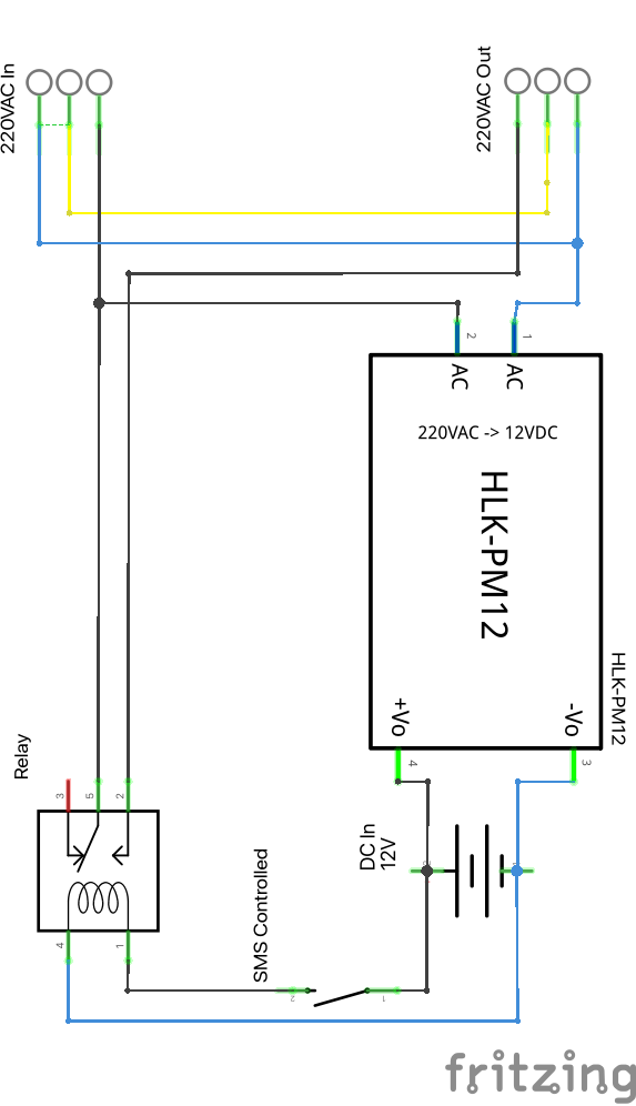
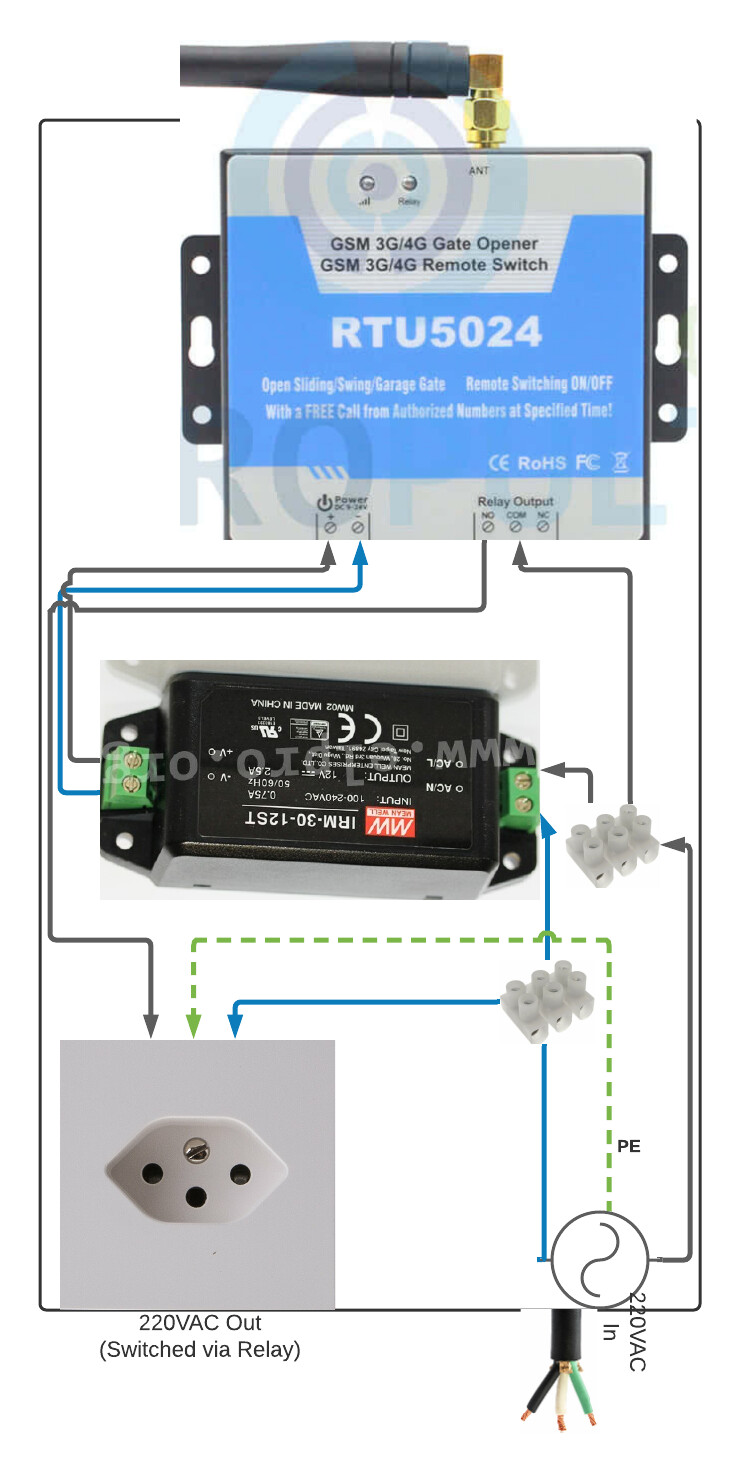
I have now updated my schema to use a AC/DC converter that also does transformation. Thanks for your clarification. Pins 3 and 4 are connected to a DC power source symbol. This symbol is redundant in the schema. I chose to draw it, because it visualizes the 9V DC port of the RUT5024 chassis.
Regarding the 220V output: I could not find any 3-pin power plug part in Fritzing :(. I have now replaced it with the same symbol I used for power source. That way PE and neutral can be separated on the output power plug symbol.
It looks like the remaining question is, whether it is okey to connect / split the cables between input and output like I imagined.