Hi,
I am creating a rather simple device that requires some electronics and involves 220VAC voltage. Because the device should work unsupervised for a long period of time and high voltage is involved I would like to have my concept reviewed. I am new to electrical engineering … and therefore also have a few questions left.
The project:
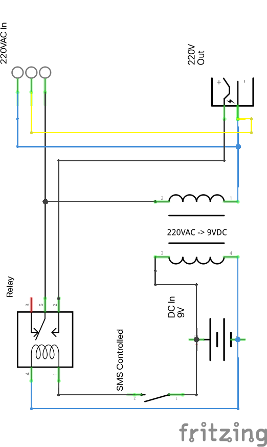
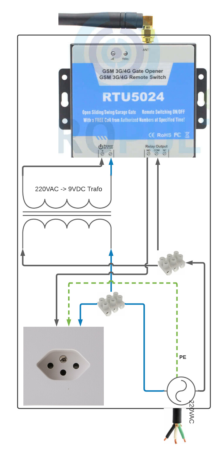
I have a GSM modul (to send / receive SMS, http://www.RTU5024.com) that I want to use to switch on/off a 200VAC power source. The RTU5024 has a relay and a GSM modul built in. It only requires 9V to operate.
My questions:
I decided to use the high voltage power source to power my RTU5024 (converted from 220VAC to 9VDC). I have read, that it is recommended to separately power (or use optical isolation) the RTU5024. Why is that? Is it ok like I designed it?
In my design I did not connect my chassis with the PE. I thought that is not required, because my chassis will be made out of plastic or wood. Should I connect my chassis with PE anyways?
Is there something I have to take care of regarding the cables / connections?
What else do you thing about my circuit, did I miss something? Since I am new in this area I am sure I missed some bits here and there
The correct transformer will convert 220VAC to 9VAC. Not 9VDC. AC to DC needs “rectification”. Typically a full wave bridge rectifier. Plus filtering to get “smooth” 9VDC, not pulsed 0 to 9V. That is what the wall wart will do. Creating good AC to DC power supplies is a whole topic, with considerations for specific cases, about how “good” the DC output is. A wall wart with enough capacity (the maximum output current) will work fine for all but the most specialized cases.
The english for that link shows a part that accepts 24 to 85 volts AC input. Not 220 volts.
Your diagrams do not really show the ac/dc module. I was basing my comment on those and your text description. You said “transformer”, and that is always/only ac to ac. The diagram “looks” like a transformer is being used, but showing ac to dc. If that part is really a module (with proper input and output), then maybe it will work. Do you have something doubled? That image shows what looks like a battery symbol across pins 3 and 4 of that ac to dc conversions. If that is the mentioned module, there should not also be a battery.
Mains power is not my area, but I am not comfortable with having ground/neutral plus one side of the 220 volt line connected directly from input to output. You are only switching one side of the mains power. Depending on the situation, I believe that there can be “power” between neutral and one side. In fact, it appears you are tying the input neutral to the unswitched side of the mains, turning the 3 wire mains into 2 wire. Not something I would do without research and testing.
The english page indeed contains a typo. The free text description is wrong (a missing trailing 0), the technical specs are correct (align with the linked PDF datasheet).
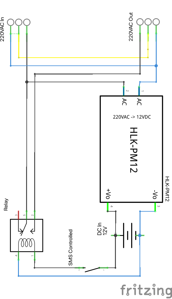
I have now updated my schema to use a AC/DC converter that also does transformation. Thanks for your clarification. Pins 3 and 4 are connected to a DC power source symbol. This symbol is redundant in the schema. I chose to draw it, because it visualizes the 9V DC port of the RUT5024 chassis.
Regarding the 220V output: I could not find any 3-pin power plug part in Fritzing :(. I have now replaced it with the same symbol I used for power source. That way PE and neutral can be separated on the output power plug symbol.
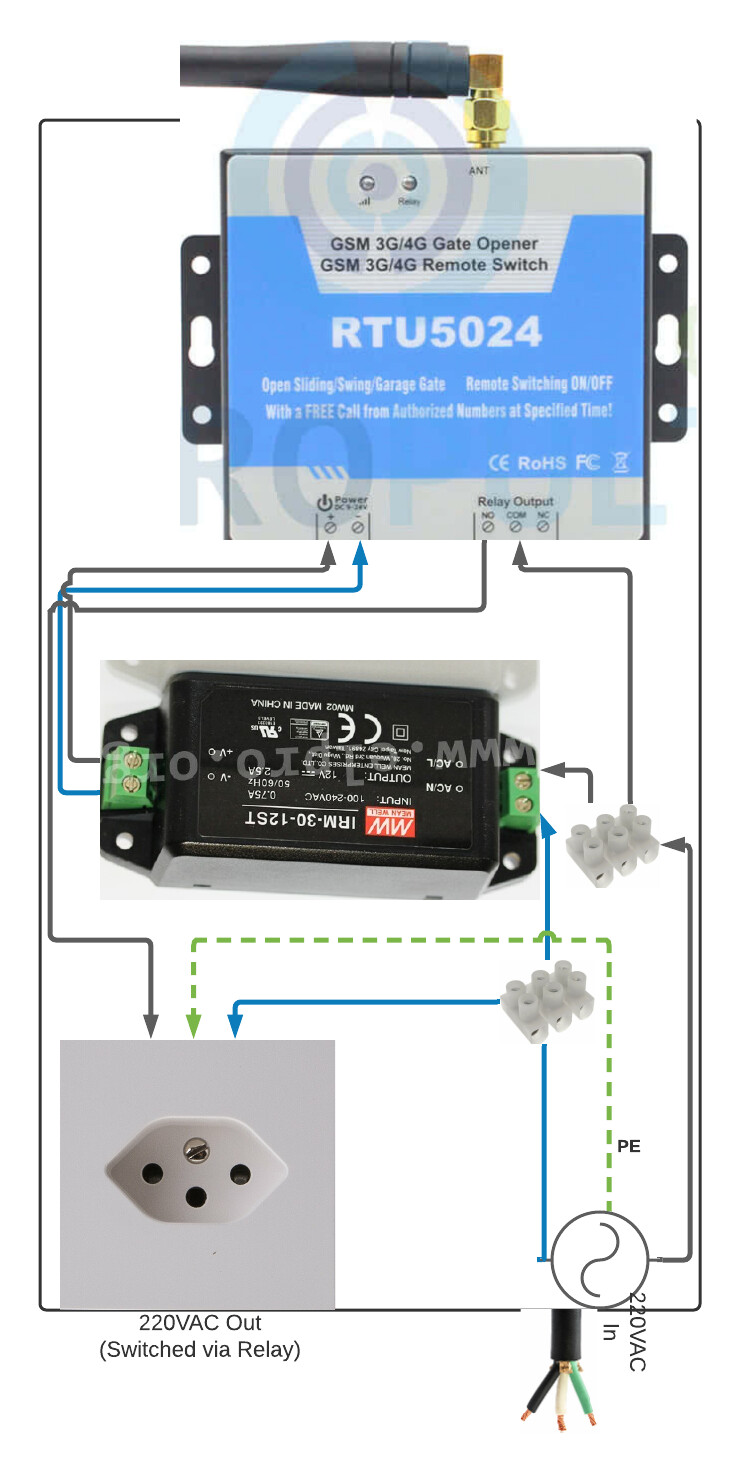
It looks like the remaining question is, whether it is okey to connect / split the cables between input and output like I imagined.
This looks like it should work. The switching only one wire of the 220V source is common, but not necessarily legal. You need to check with an electrician familiar with the regulations in your country to make sure this setup is legal. If it is not, and someone gets hurt you may be legally liable. We don’t know enough to advise you.
If you need or want to switch both sides of mains power, replace the SPST relay with one that is DPST (double pole instead of single pole). That has 2 sets of contacts, so can switch both sides. There are some DPDT (double throw) relay parts in Fritzing. I did not see with a quick check any DPST, and did not see any rated for 220VAC either. But that was a quick check. For diagramming purposes, you could use DPST or DPDT, as long as used a correctly rated relay in the actual project.
One more thing to take in to account: the RTU5024 output relay is rated for 3A. Assuming you are driving a gate opening motor (which appears to be its purpose) you need to check that the load takes less than 3A at 220V.
I am a qualified electronics engineer and I would strongly recommend you use an off the shelf power supply to supply the 9vDC you need. Power supply design is very important and complex and you need to take account of any fault conditions such a short circuits and transform faults. Failure to consider these could lead to fire, electrocution and other risks. As a novice I think it would be best to play safe and limit your learning to the low voltage side of the circuit.
One more thing to take in to account: the RTU5024 output relay is rated for 3A. Assuming you are driving a gate opening motor (which appears to be its purpose) you need to check that the load takes less than 3A at 220V.