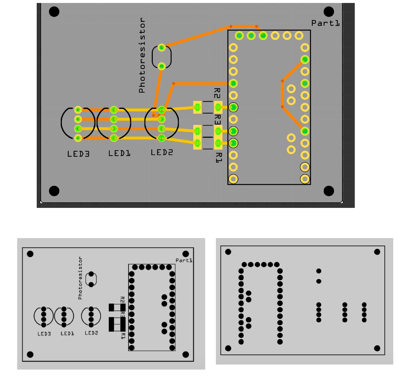
Working on my first pcb project. My breadboard view, schematic, and pcb look good. However, when I go to fabricate, it shows that no holes will be drilled for the three resistors. (maybe i have selected a resistor that gets soldered to a pad?) If so how do I change this to a simple resistor that requires two holes like in the breadboard layout? Thank you!
Your best bet is to upload the .fzz file of the sketch. It looks like the resistors are custom parts rather than core parts, and thus may be wrong but it is impossible to tell from just pictures. Upload is 7th icon from the left in the reply menu.
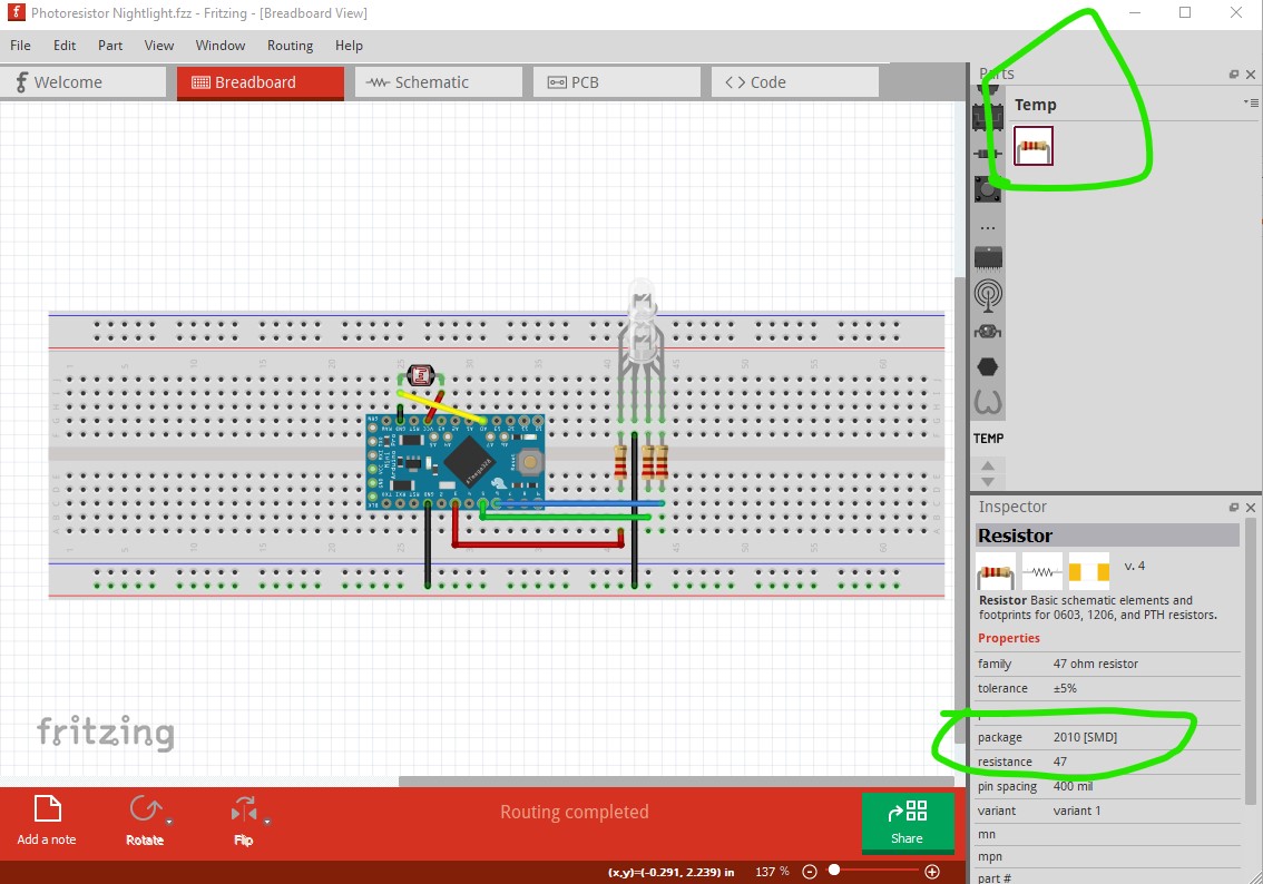
I think I may have made this a custom part by trying to change the level of resistance… I will go back and try to use the custom part. I have attached the file. Thank you!
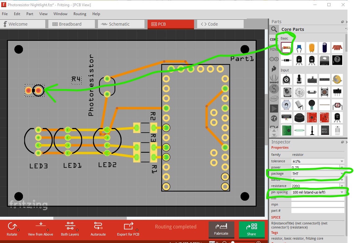
Problem solved. Thank you so much. I went back and changed the resistor to a core part and it worked great. Thanks again for your help and quick response.
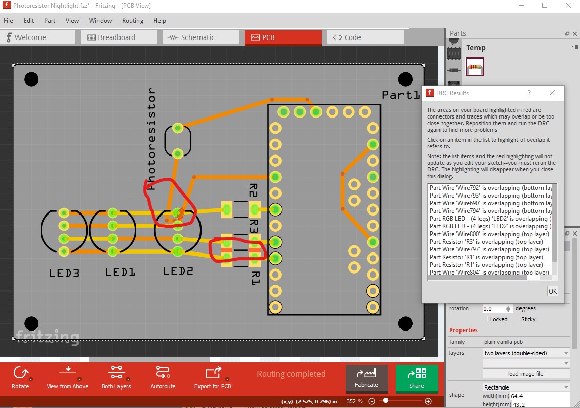
the custom part shows in the temp parts bin (as it is not in core parts) and shows SMD in inspector on the lower right. After that DRC (routing->Design Rules Check) indicates you have a number of overlaps that will cause shorts and make the board useless.