Anyone can help me to rerouting my pcb?
hydroponic.fzz (110.6 KB)
You have a number of problems: there is an overlap when you run DRC (routing->Design Rules Check)

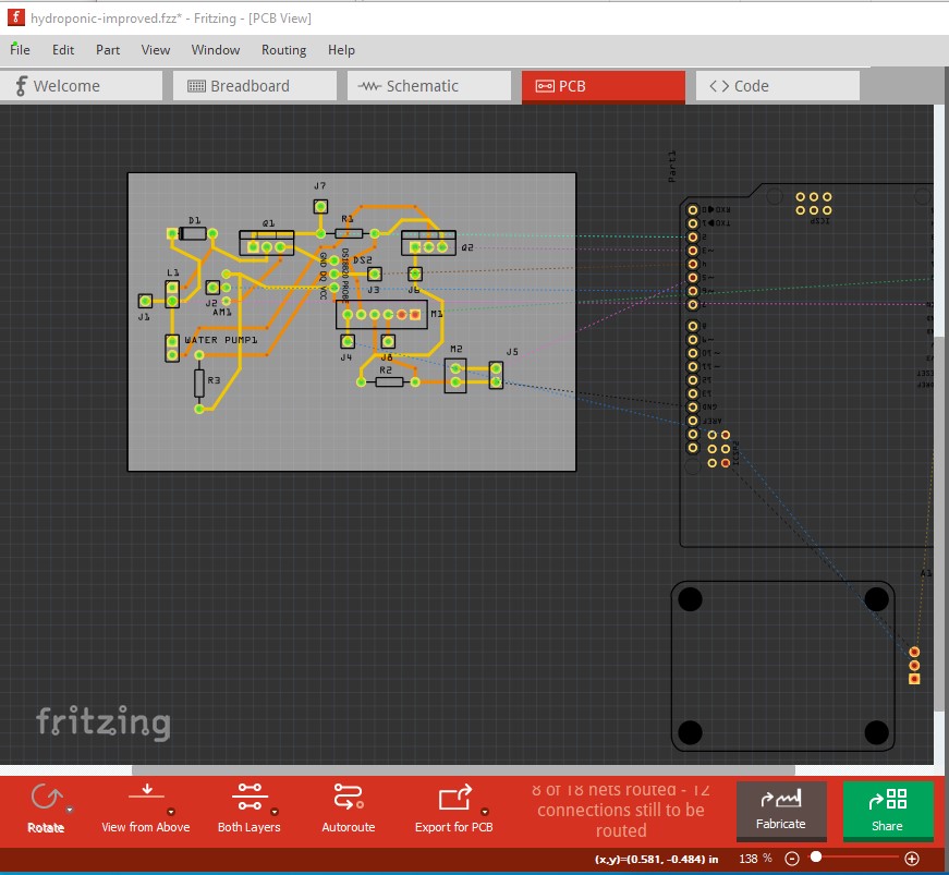
most of them can be cleared by moving the pcb borders, but the trace (circled in red here) is to close to the FET (indicated by the red bar on the square trace) moving the trace down one position fixes that.
The next problem is that the off board connections don’t have anywhere to connect to (the pad for the part will be taken up by the wire for the part!) so you need to add single pin headers (outlined in green here) to provide a connection point for the wires. Here I also routed the traces off board to complete routing (so you can see that the connections are correct and DRC passes!) For the actual board, delete the off board traces like this
that is reflected in this sketch
hydroponic-improved.fzz (116.5 KB)
You may want to add labels that identify the off board connections by name to make wiring easier (I didn’t do that here!)
edit:
In case you wanted to include the Uno and sensor on the board, you need to increase the size of the board in Inspector (the lower right window) like this:
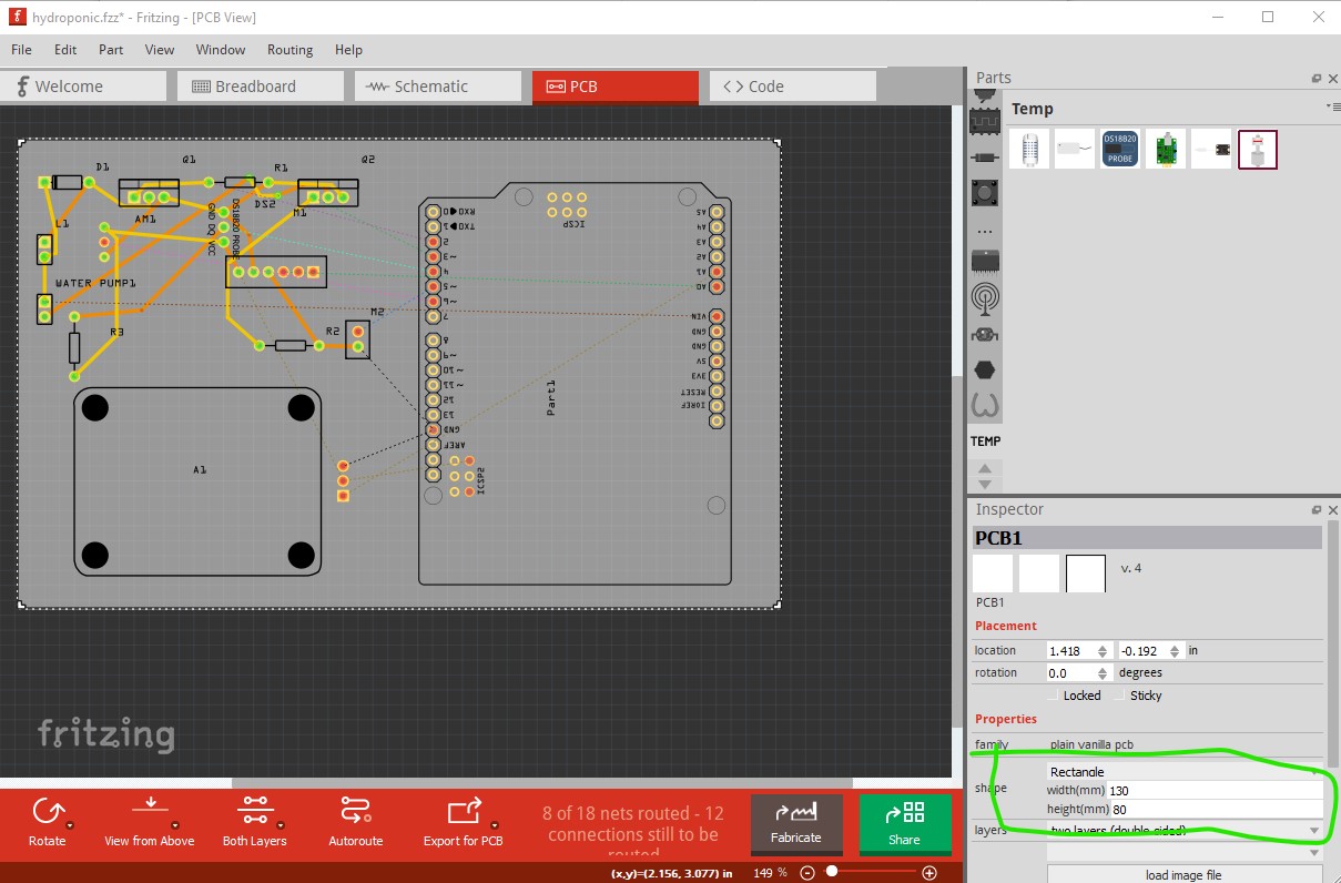
where the size is circled in green. Then route the unrouted connections (and remove the connectors I added which aren’t present in this sketch!) You would need to drag holes in to the sketch for the mounting holes on the sensor and the Uno which are not drilled by default though.
Peter
Very very thank you for the new knowledge for me. i will take a note sir.