I’m working on a project that uses an XT-120 2+4 connector, both male and female, and I haven’t been able to find an existing Fritzing part for this component anywhere online.
To create a new part in Fritzing, I understand that an SVG is required, so I am attaching the SVG I made. .
In this SVG, the connector is represented with six colored rectangles, and I need the final Fritzing part to include one connection pin for each of these rectangles.
These represent the six wires used by the connector:
Power: red (+) and black (–)
Data: green, orange, blue, and yellow
Unfortunately, I haven’t been able to find a datasheet for this connector model. The only technical information available is an image with the measurements included in the product description of the item. I am attaching that as well, in case it is useful for creating the part:
If someone could help me create the .fzpz part for both the male and female versions—using the SVG and the wire mapping described above—I would greatly appreciate it.
Just to clarify the intended use:
All six pins of the XT-120 (the 2 power wires + the 4 inner data wires) will be connected to a PCB in my design.
However, only the four inner data pins are intended to be used on a breadboard when prototyping. The two power pins (positive and negative) can’t be used on a breadboard due to their current rating, so those will not go to a breadboard at any point—only to the PCB.
My goal in Fritzing is simply to create a part that represents the full 6-pin connector, so the schematic matches the real hardware.
As for documentation, I haven’t been able to find an official datasheet either. The only technical references available are the product images with dimensions:
I’d appreciate any help or guidance to create the correct Fritzing part for this connector.
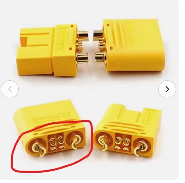
It is unclear to me that this will fit a pcb at all. It appears to be intended to solder wires in to not attach to a pcb, As you note the pcb will likely not take that kind of current (only something like 12 Gauge or higher wire will.) There are no mounting holes that would allow you to screw it down to the pcb and it would thus likely pull out (and destroy the pcb) when the plugged it.. It is possible (but mostly pointless) to make a connector intended to take wires but pcb use seems unlikely. This image from a site selling them illustrates the issues.
There is nothing that could anchor the connector to the pcb, and thus it is likely to be torn out of the board when disconnected. From the shape of the pins they intend that you solder wires to the connector. If you do that you can then run the wires to pads on the pcb.
 .
.