I’ve been looking at the datasheet for this thing but never found anything. Is that possible to make part creation only with this picture?
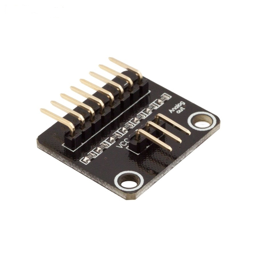
Would need to know what each of the input pins are. It would also be best to know what the exact measurements of the PCB are, in inches (preferred), or centimeters.
Randy
1 Like
The input of each pin is the whole keypad output.

Datasheet 4x4 keypad membrane
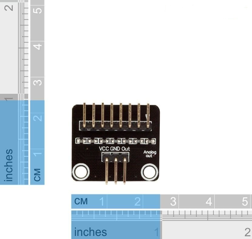
It’s exactly as in the second picture
Width : 0.95 inches
Height: 0.9 inches
To me, it looks like the part is .9 inches high, but that is because the pins over hang the outside edges of the pcb. So the pcb is a bit smaller and I made the pcb silkscreen for this part a bit smaller - .085 inches height.
Anyway, I assume you won’t need connectors for the pcb, correct? What should I name this part? Do you have a link to this part?
Randy
1 Like
Actually, I need it. but since there’s no datasheet, I only know the function of 3 pins below. As for the 8 above pins, i didn’t know exactly hw this works.
You can name it as in this title thread.
If you need copper pads on the pcb, I need to know how far apart the top and bottom rows of connectors are.
Randy
1 Like
This looks like your best bet for information. It appears to convert the key presses in to an analog voltage on the the output to allow a single pin to interface to the key board. The connectors are almost certainly 0.1in headers and this pdf should give you the layout if you scale it (it may also already be at 1:1 scale!)
It also has the pin names.
Peter
1 Like
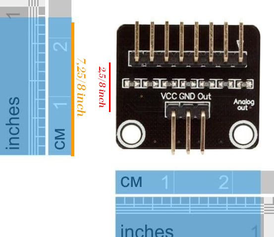
Yellow grid are 7,25/8 inch or 0,9 inch
Red grid are 2.5/ 8 inch or 0.3 inch
Thanks you so much man. This really helpful
If I was making it, I would put in a 3 pin 0.1 header as pcb and suppress (by removing the copper0 and copper1 layers in the fzp file) the 8 pins for the keypad. They are going to connect to the keypad and shouldn’t need to appear on pcb, as only the power, ground and signal output need to connect to the board from the micro. There probably needs to be a 3pin cable between the connector and the board (the pins don’t appear long enough to connect in to a pcb vertically …)
edit: There is a mechanical drawing (without connector positions though) here:
and a schematic here:
Peter
Hey thanks Peter, your links clarified things a bit for me.
And thanks for the advice on pcb, makes sense.
Here’s the part:
Keypad Adapter-Analog.fzpz (13.1 KB)
Randy
1 Like
The part looks good!
Peter
Woah… That’s awesome man.
Thank you so much