Not a bad part, but a few problems. I ran it through FritzingCheckPart.py which has these complaints:
Error 69: File
‘svg.breadboard.prefix1_c907a3885c7d634196fda568e1ce46fc_29_breadboard.svg.bak’
At line 9
Found a drawing element before a layerId (or no layerId)
Error 74: File
‘svg.pcb.prefix1_c907a3885c7d634196fda568e1ce46fc_29_pcb.svg.bak’
At line 19
Connector connector4pin has no radius no hole will be generated
Error 74: File
‘svg.pcb.prefix1_c907a3885c7d634196fda568e1ce46fc_29_pcb.svg.bak’
At line 20
Connector connector3pin has no radius no hole will be generated
Error 74: File
‘svg.pcb.prefix1_c907a3885c7d634196fda568e1ce46fc_29_pcb.svg.bak’
At line 21
Connector connector2pin has no radius no hole will be generated
Error 74: File
‘svg.pcb.prefix1_c907a3885c7d634196fda568e1ce46fc_29_pcb.svg.bak’
At line 22
Connector connector1pin has no radius no hole will be generated
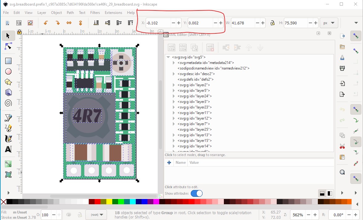
The first error is a missing layerId in breadboard. The result is your part will not be exported as an image (jpg, png, svg, etc.) To correct that you need to reset the breadboard svg to start at 0 0 and collect the entire svg in to a group named breadboard. In the original svg, we see that x and y are not both 0 as they should be ( the edges of the document will get truncated which probably doesn’t matter in this case.) to fix that in Inkscape do Edit->Select all then Edit->Resize Page to Selection.
then Object->group to make the entire document a group and rename that group to breadboard like this:
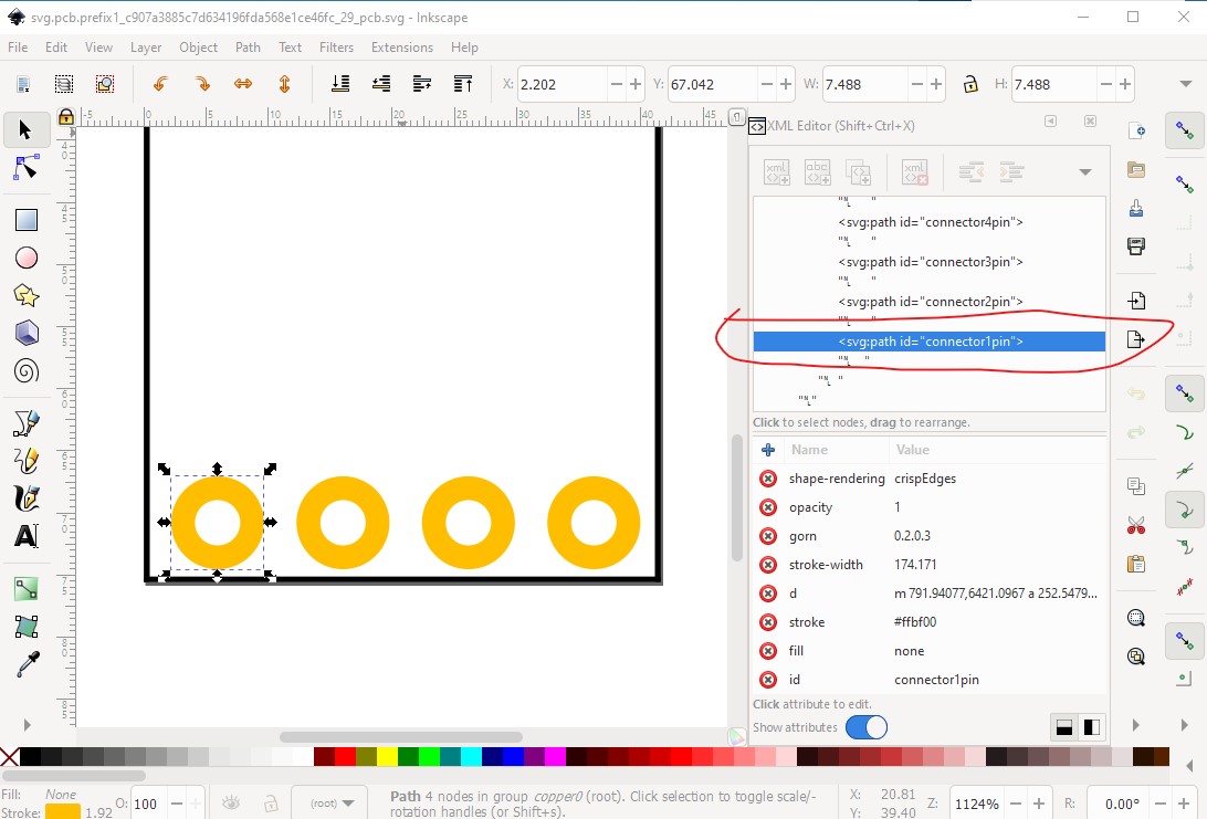
The complaint about no hole in pcb is a false positive. The pads in the pcb svg are paths which in this case happen to work correctly because the path describes a circle, but many paths that are not a circle (such as an oblong pad) will not correctly generate a hole, so it is preferable to use a circle with a stroke width of 20 thou as the pad.
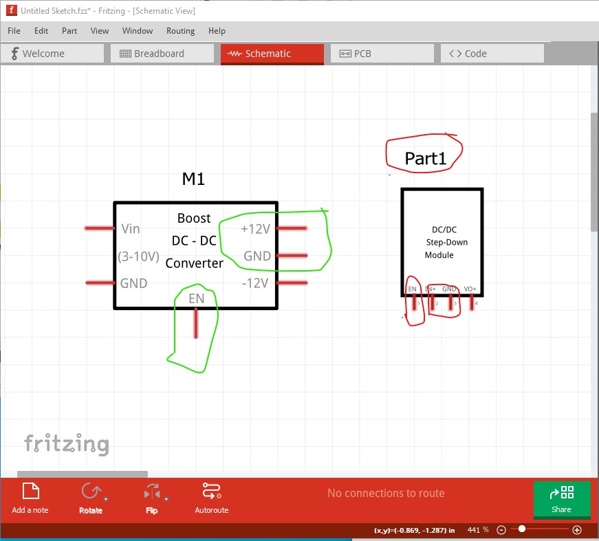
Schematic has several problems, here I have added another converter with a correct schematic:
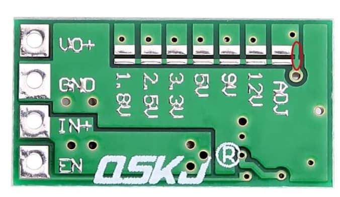
The pins want to be 0.1in long and spaced 0.1in apart to match most other parts and align to the grid. Usually inputs (such as power) are on the left, and outputs on the right. As noted pins are 0.1in wide and spaced on 0.1in boundaries. As well it is preferable to have a label field (here set to M for module) in the fzp file to avoid the default Part designation.
Peter
 )
)