It can’t be implemented in parts (with one exception which affects the entire pcb) that funtion isn’t (and I think, can not be due to how gerber processing works) be done in a part that can move on a board. The directions in the tutorial will only put slots in an entire pcb not a part.
Which creates a base PCB that has the slot in it just like the manual process. You can only have one of them in a sketch and can’t put it in to a part that you can move around on the board. This is the special case where a “part” can have a slot, but is in fact a short hand way of using the standard slot creation tools with the same limitations.
Hello,
Thanks for the responses.
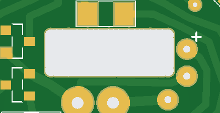
I got it done with the built-in hole feature.
I created a rectangle hole with it.
How: very simple, Place a 2x a hole of say 4mm.
Now place another 2x a hole of 4mm but move it 2mm so that the V is filled. Repeat this as often as necessary with a hole of 1mm until you have a nice straight cutout.
Maybe not the intention of the function but it works.
If you would upload the sketch (the .fzz file you saved the sketch in, upload is 7th icon from the left in the reply menu) I will have a look at it. If I understand what you did, you simulated a square hole with a series of overlapping holes. While this sort of works, the problem is when the board house drills it it tends to break drills so they may reject the gerbers as not meeting production standards. The slot method uses the contour.gm1 file to mill a square hole, the limitation in Fritzing is you can’t do that in a part (I assume it makes gerber processing too complex but don’t really know.) This has been suggested before and that is when someone raised the points that it doesn’t cut smooth slots (the drill leaves an arc in the board material between holes) which you can manually file off, but the main objection was the drill breakage.
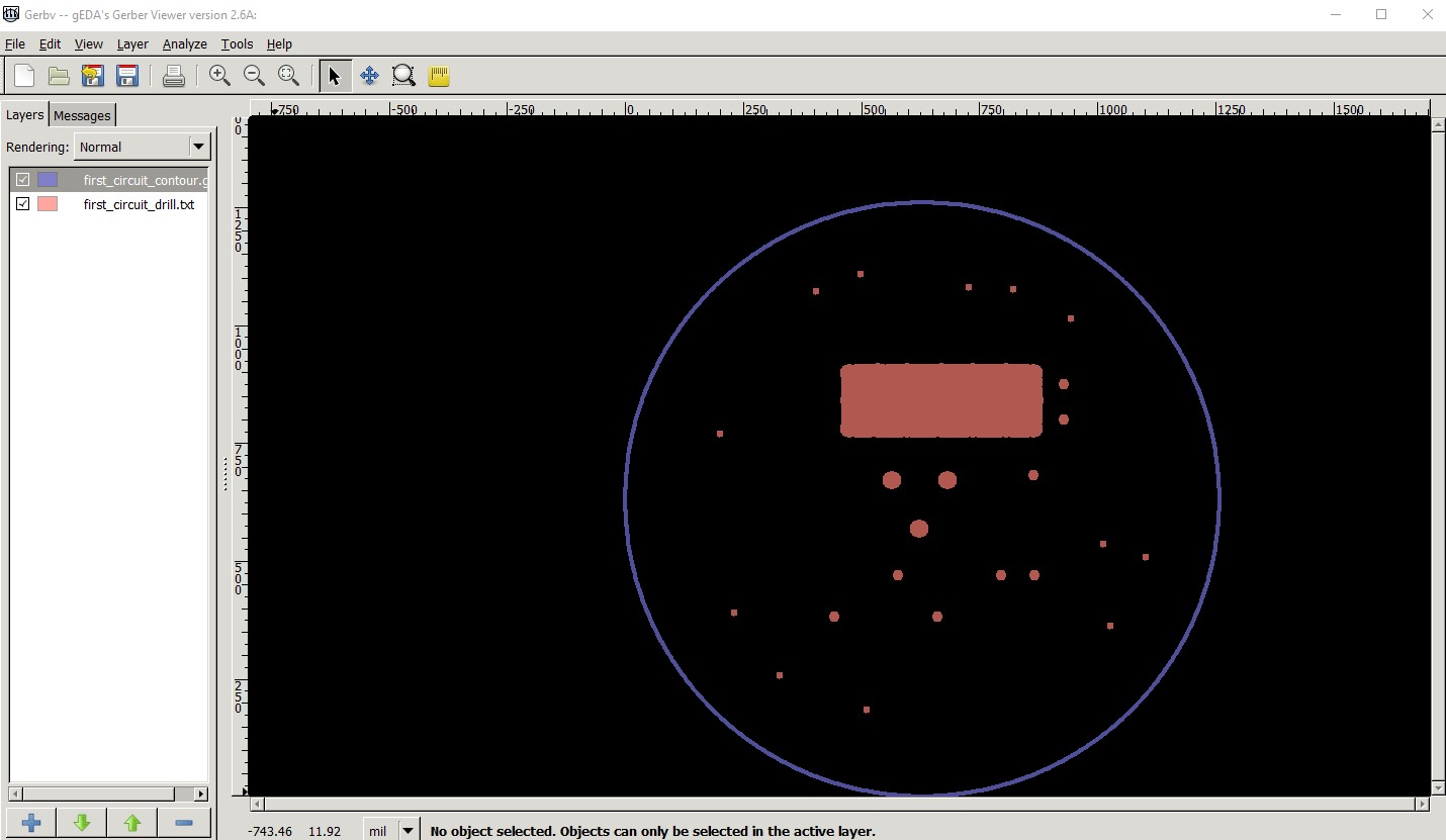
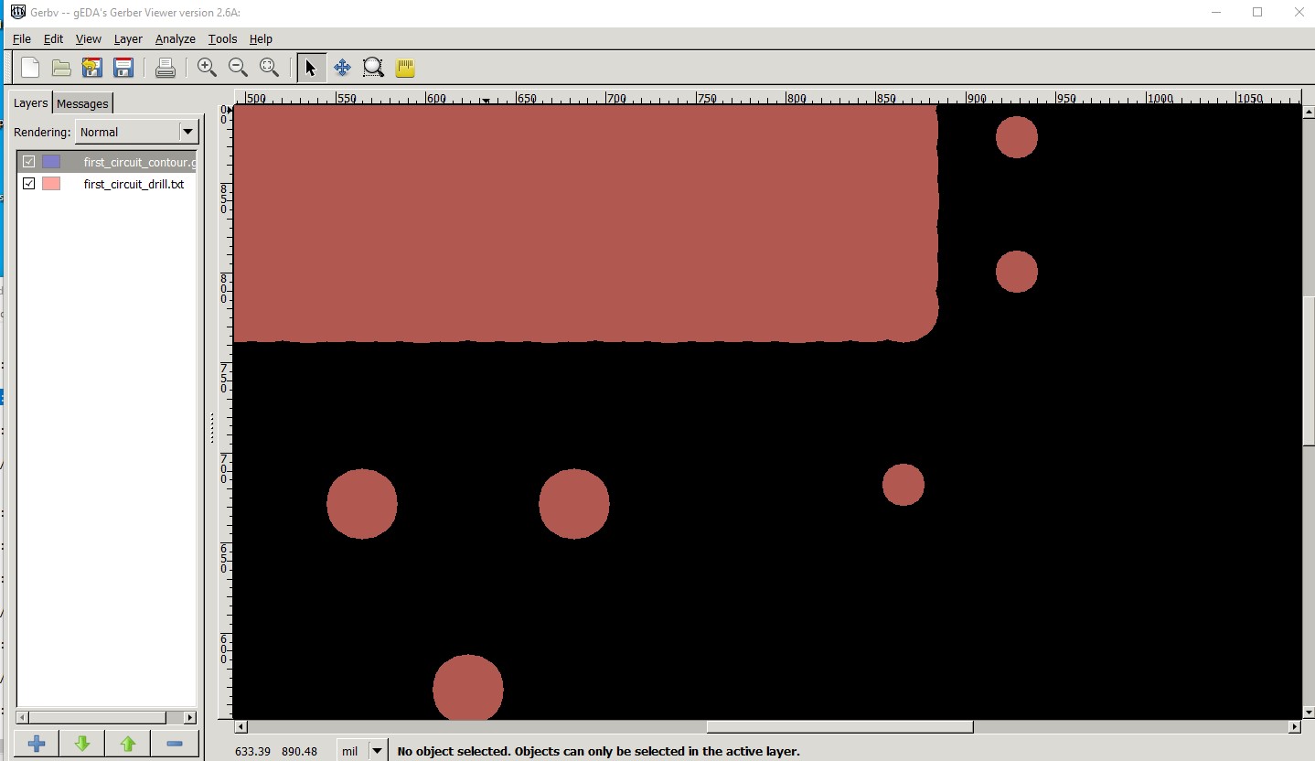
OK, I suspect the board house will probably reject this as the holes are overlapping. You could submit the gerbers and ask them if they can do it though. This is your sketch exported as gerber and then displayed (contour.gml and drill layers only) with gerbv
this is a zoomed in section of the rectangle. I expect they are going to have a problem with drilling this as depending on the drill order there likely won’t be enough fibreglass to let the drill start (which leads to drill breakage.)
With only 1 slot in a fixed place, while it is a PITA to do a slot will work here and mill a slot (which the board house will be a lot happier with I expect!) You need to modify the circle svg to add a differenced reverse path for the slot in a fixed place on the circle (exactly what the slot code is designed to do.)
the main thing is the path that describes the slot needs to be running the opposite way to the direction of the circle but it should be able to do what you want I expect with a lot more success than the drill method.
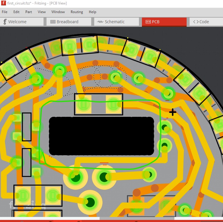
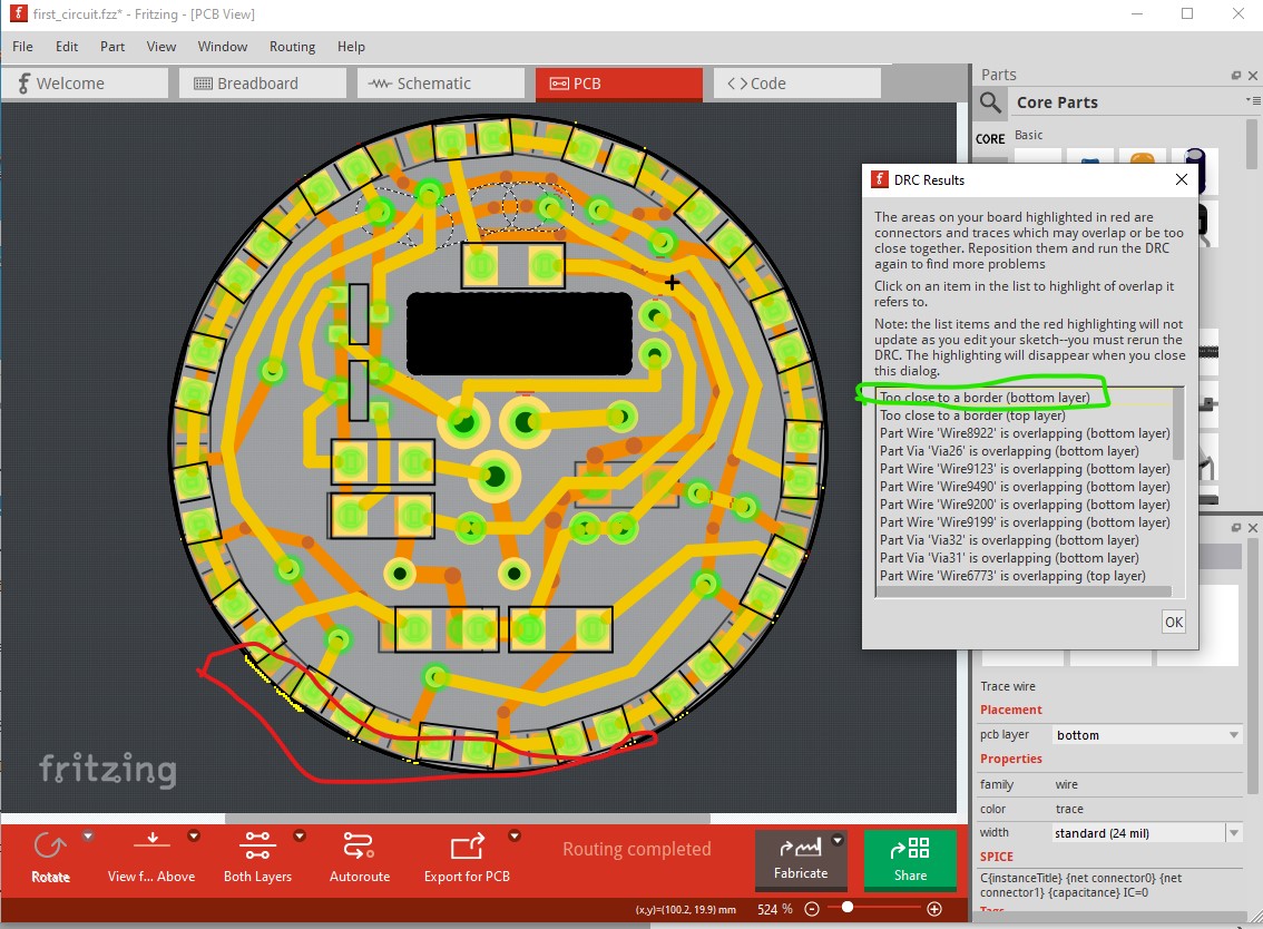
That said as a non related side issue you pcb has DRC issues. Click on Routing->Design Rules Check to run DRC. After doing that click on a line in the report and Fritzing will highlight were the issue is. In this case I clicked on the first line and it is telling you the areas highlighted yellow (in the red circle here) are to close to the edge of the board. You either need to move the traces in a bit or make the circle slightly larger.
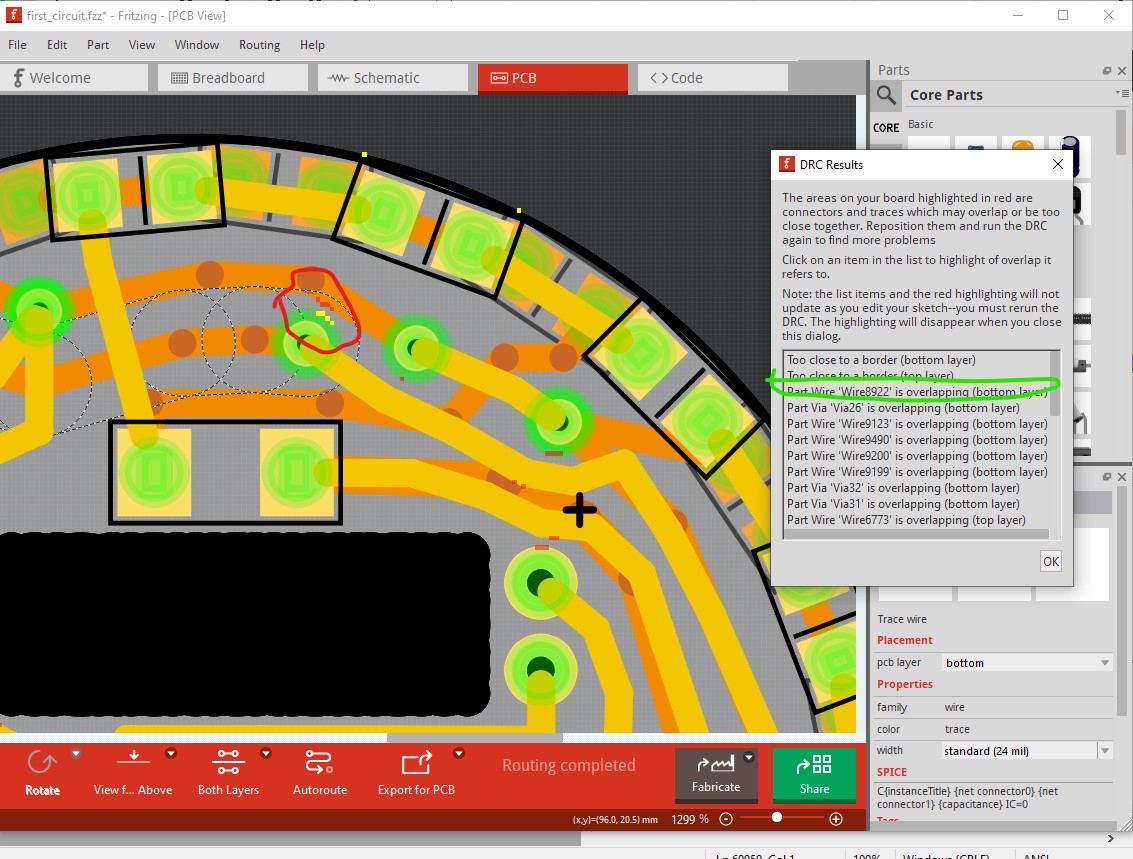
Then I clicked in the 3rd line (a trace problem) which says the trace is too close to another trace. To fix that you need to move the trace slightly further away from the trace it is too close to. The red markers (which can be hard to see, you may need to zoom in to see them!) indicate other sections that are too close.
I will work on the improvements, I now understand how the DRC works. I will ask the PCB maker if they can mill out the rectangular hole instead of drilling.
I believe (but check with your board house!) that if the contour.gml file is supplied with a slot in it then the slot will get milled. It has worked the way for a number of folks I have helped getting slots created (I haven’t done a slot in a board my self though.)