Its been quite some time since the release of the tiny Raspberry Pi Zero and its about time we had a part for it.So here you go.
http://fritzing.org/projects/raspberry-pi-zero
I hope you all like it 
Its been quite some time since the release of the tiny Raspberry Pi Zero and its about time we had a part for it.So here you go.
http://fritzing.org/projects/raspberry-pi-zero
I hope you all like it
How to add it in software?
thanks
have you tried drag and drop?
The schematic is off. The pins are far too small, and scrunched together. But for some reason the breadboard version is fine.
I wish I had realised this before sending a design to be made. As a result, I now have 3 useless boards. My own fault for not checking properly.
The zero available in the parts bin appears to be correct at first glance (I didn’t go as far as to produce gerbers and check hole sizes though). I’d start there.
Peter
Can you update the part file so the pins are spaced properly?
I could if I saw anything wrong with it. However the one available from the core parts bin by searching for “raspberry pi zero” is correct as far as I can see so you should use that. I might be tempted to change schematic to reflect the layout of the GPIO connector (i.e. 20 pins either side with multiple power pins), but the current one appears perfectly correct to me.
Peter
The spacing of the gpio pins is too small. If you open the regular raspberry pi and the zero, you will see the size discrepency
So it is (didn’t look close enough). They look to have used 2mm instead of .1 in pcb. I’ll post a corrected part in a bit.
Peter
I owe you a beer. This has been an all day thing trying to figure out a work around.
Where will you be uploading the revised file to?
Here once I can get one to work :-). This is much more screwed up than I first thought. I replaced the pcb svg completely and it looks like breadboard is managing to carry a translate over in to pcb with the result the connector is still too small, even though the svg is now a modified version (to change the silk scrren) of the PI 3. I’ll continue beating on it, it may be that I need to redo breadboard and schematic as well to get it to work.
Peter
Progress! I replaced the other 3 svgs (other than pcb) with the pi 3 versions and now pcb (without any changes) is properly scaled, it still isn’t exporting correctly but for sure breadboard is also broken somehow and managing to break pcb which is weird. I’ll continue poking (at the rp 4 for now, to make sure it exports correctly and I’m not copying something that doesn’t work  ).
).
Peter
Thanks Peter, I spent all day putting this pcb together, and when I test printed it I had a head to desk collision. I’m glad you are getting it done correctly. I’m using the zero w which is the same foot print.
Here is a part that mostly works (with the warning that I don’t know why it works ). All I did was group the components in breadboard because with only the connector present it worked, indicating something in the non connector part of breadboard was causing the problem. I was intending on removing the components one at a time til it worked to identify which one it is, but to my suprise when I tried it it seemed to work. I think the bus stuff may have problems, but I’ll look at the tomorrow. Also the connector holes are .040 when they should really be .038 but thats minor. It exports on .1 centers correctly in the gerber which is the important part.
See: Raspberry Pi Zero Fritzing Part
Peter
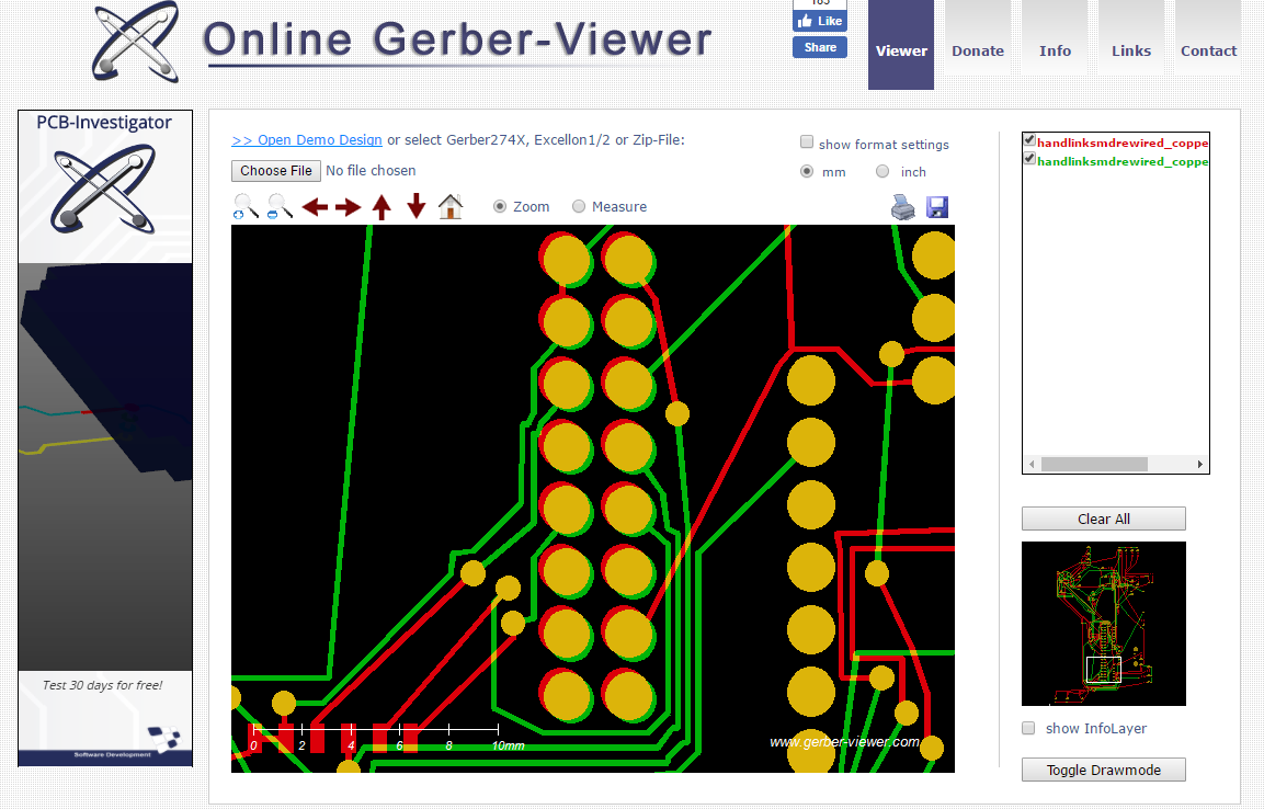
Yeah, looks better. I did an export to gerber. Take a look at the copper. There seems to be a slight offset of the gpio pads. It looks as if there is 2 pads, with one slightly ofset down and to the right
That’s odd. I just downloaded the file I uploaded (to make sure I had uploaded the correct one last night ) and cleared my gerber directory to make sure no old files in there, then loaded Raspberry Pi Zero_fixed.fzpz and created gerbers. They look fine in my local copy of gerbv. I zipped the directory of gerbers and renamed it to fzpz (so it isn’t a real part just unzip it) and uploaded them. I’m on Win7 although that shouldn’t make a difference. This part has been so strange its possible there is yet another problem still here though. The pcb file is the one from the pi 3 which of course may have problems too. I’ll poke at it more, there are a few more things that should be corrected before submitting a correction for core (I am going to try and figure out how it breaks pcb anyway, just because I want to know, I think that may be a fritzing bug).
gerber.fzpz (18.3 KB)
Peter
Yeah, I was wondering why someone wouldn’t have just copied the part of the old pi file that works, onto the new svg. Seems like that is the easy way to go.