OK, I used copy and paste via Inkscape from your updated breadboard in to my original to move all your changes (I hope anyway!) across:
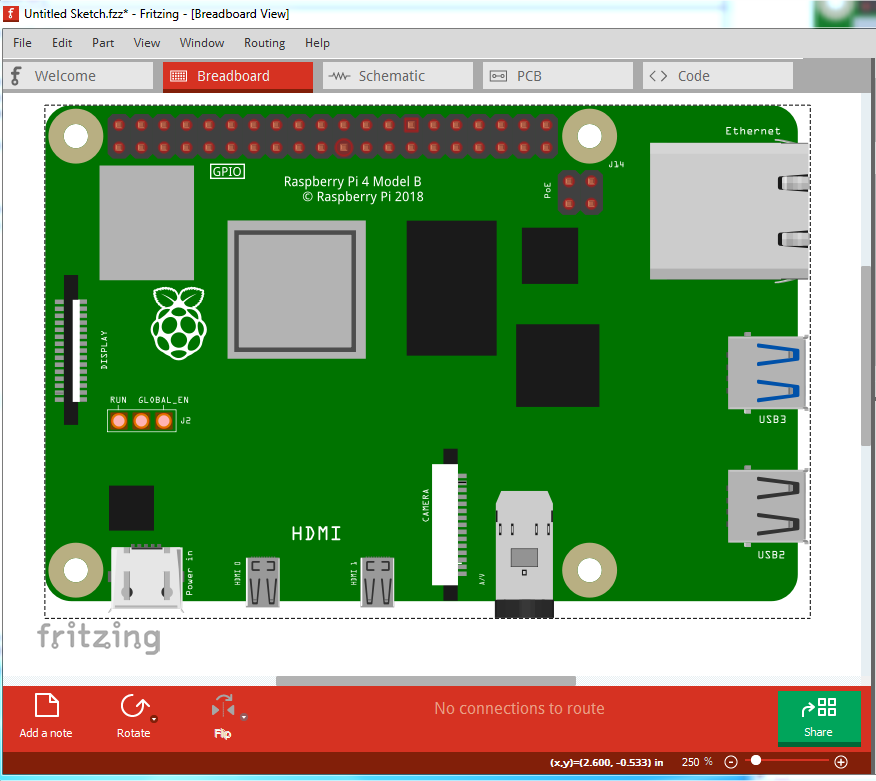
breadboard:
Move the GPIO and PoE connectors down to be centered with the mounting holes as they should be (and are in pcb).
Replace the display and camera connectors with your better versions and place them appropriately.
move the run global_en jumper block up to the same position it is in in pcb (overlayed the pcb svg to get the placement correct)
replaced the 2 HDMI Mini connectors with your HDMI micro connectors and added the larger HDMI label
Replaced both USB connectors with the ones from your svg and added the labels for both USB ports and the ethernet (which when I looked closely at my 4B I see are really there :-), good eyes!)
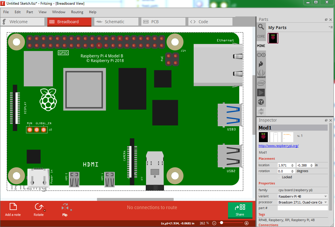
Increased the size of the Raspberry PI logo a bit to make it more accurate with the one on the board. So breadboard now looks like this:
which came from this new part:
Raspberry-Pi-4B-2.fzpz (39.5 KB)
So please have a look over the new part and see if you see anything else I have missed. Schematic and pcb are the same as in the original part (I don’t think you made any changes in either of those, although Illustrator looks to have  .)
.)
Edit: just noticed the camera connector didn’t get updated correctly. I’ll fix that and replace this! It is obviously my day for weird problems, the svg is correct, Fritzing is just rendering it wrong for reasons as yet unknown:
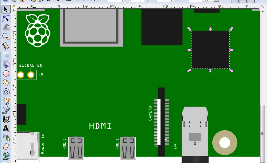
the white bar shows up much too large in Fritzing yet I can’t so far see a translate to explain that.
edit2:
Fixed. Replaced the path with a rectangle and now it renders correctly. Don’t know why that one path doesn’t render correctly though:
Raspberry-Pi-4B-3.fzpz (40.0 KB)
Peter