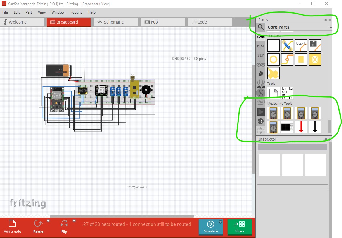
They may have been a later addition than 0.9.5 though (I think they came with the simulator.) The simulator won’t work with this sketch however as not all parts in it have spice models but the multimeter could be added to it.
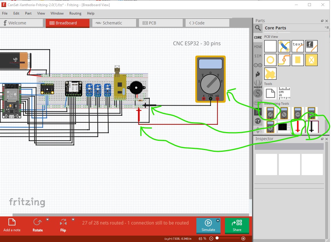
Got it! So I can’t use the multimeter with my version, but can you explain how can I connect the cables of the multimeter to the breadboard please?
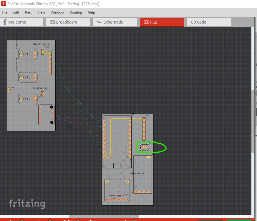
Plus, I want to insert a pluggable terminal block so I can connect the cables of the battery to the pcb board. I just need to insert it on the pcb or do I need to do something else?
Got it! Thanks for the help!
I was finally able to connect the multimeter to the breadboard, but now I don’t quite know how to make it work… there’s a “simulate”" button on the lower part of the page, but it doesn’t seem to be working.
In terms of the screw terminal, am I supposed to connect it to the cables of the battery? Because I did that, so in the pcb, I can see the connections, so I don’t know if that was really necessary or not…
I don’t think the simulator is supported til about version 1.0.1, and then only for parts with spice models and only for dc analysis (ac is in beta I think.) It would likely work for measuring the battery but likely little else as most of the parts don’t have spice models.
You can see the connection in pcb because it is connected to the battery in breadboard. The breadboard connection creates the rats nest lines in pcb (and schematic) which shows where the trace should go. Clicking and dragging the rats best line in pcb will create a trace ready to route.
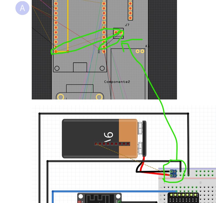
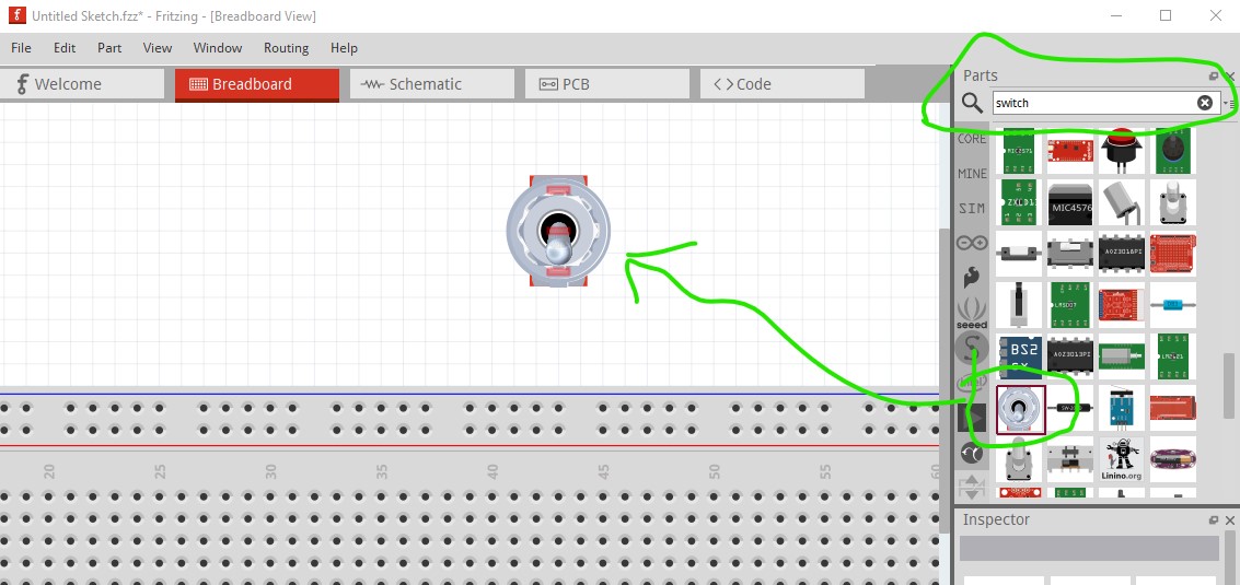
Thank you so much! But should I connect the switch to a especific cable or i just need to place it on the breadboard?
And what about the screw terminal? Do I need to connect it to the cables of the battery?
The switch needs to connect between either terminal of the battery (usual would be the + terminal) and the breadboard so when the switch is off the battery is disconnected from the micro. Just putting it on the breadboard won’t connect it to anything nor work.