I just recently downloaded fritzing and tried to design my first own circuit.
I would be really thankful if anybody would give me some feedback and tell check if this circuit is even functional.
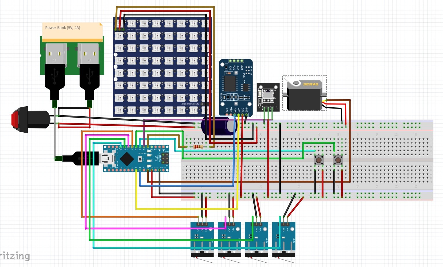
I was especially unsure about the power supply, especially since in the actual circuit I would like to use a 16x16 LED matrix.
Thank you all in advance, this forum has been really helpful!
You need to upload the sketch (the .fzz file that you saved the sketch to, upload is 7th icon from the left in the reply menu), pictures are worthless when trying to analyze a sketch always up load the .fzz file.
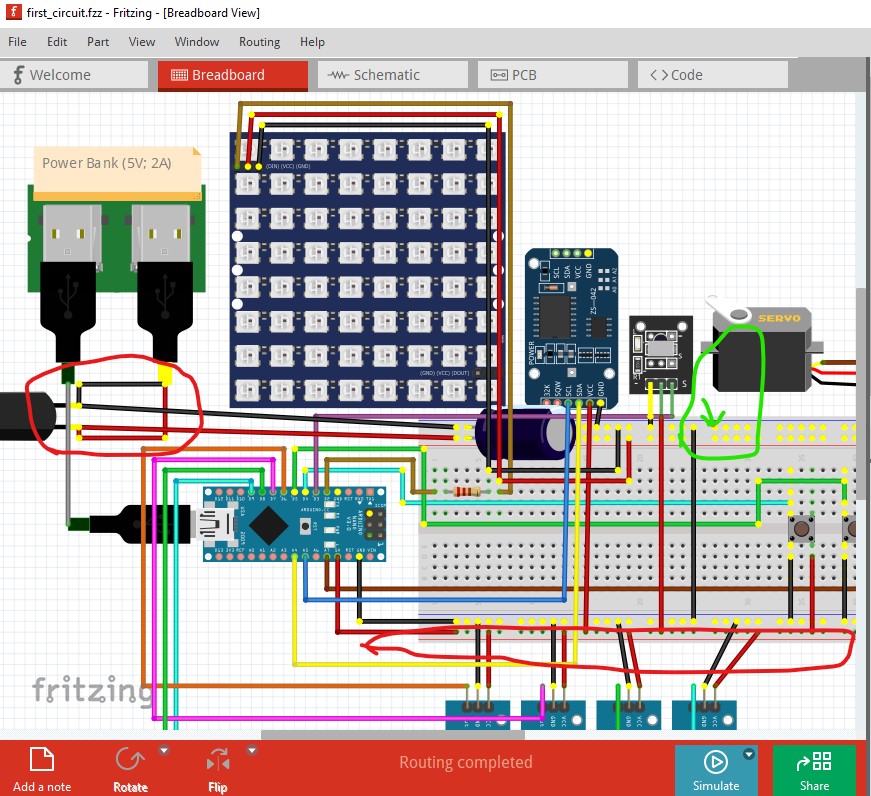
Here I left clicked on the breadboard pin with the green arrow which lights all connections in the same net yellow. That indicates you have a short between power and ground (likely on the USB connector on the right circled in red) and have no power connection to the VCC pads circled in red on the bottom of the breadboard. Another suggestion is to route schematic (which will reflect connections made in breadboard) in order to get a second look at what connections in breadboard have actually been made. It is possible to have connections in breadboard which are in fact not connected correctly. This will show up as a connection missing in schematic.
You need to move the parts in to reasonable positions then route the rats nest lines (the dotted colored lines that indicate a connection in another view i.e. breadboard or pcb in this case.)
Thank you so much for the detailed correction!
I’ll definitely check and inform myself further. Also regarding all the functions of fritzing.
Thanks again!