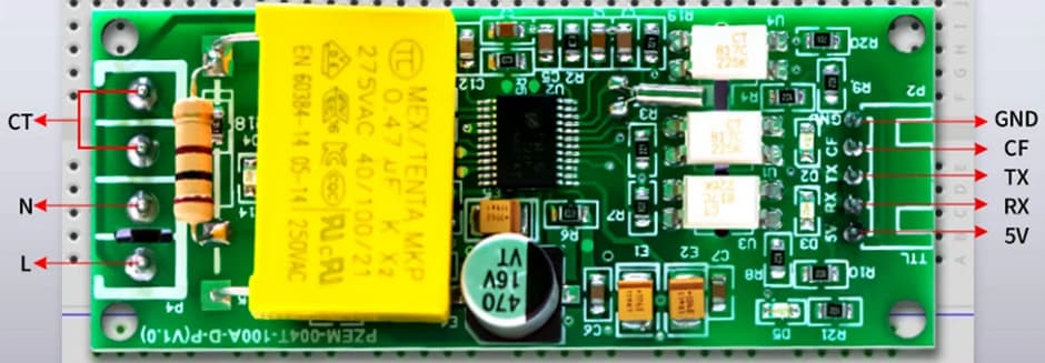
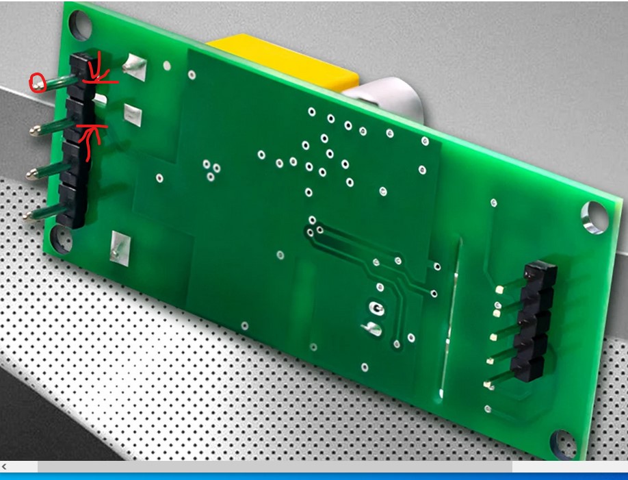
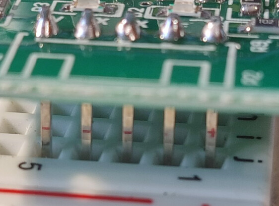
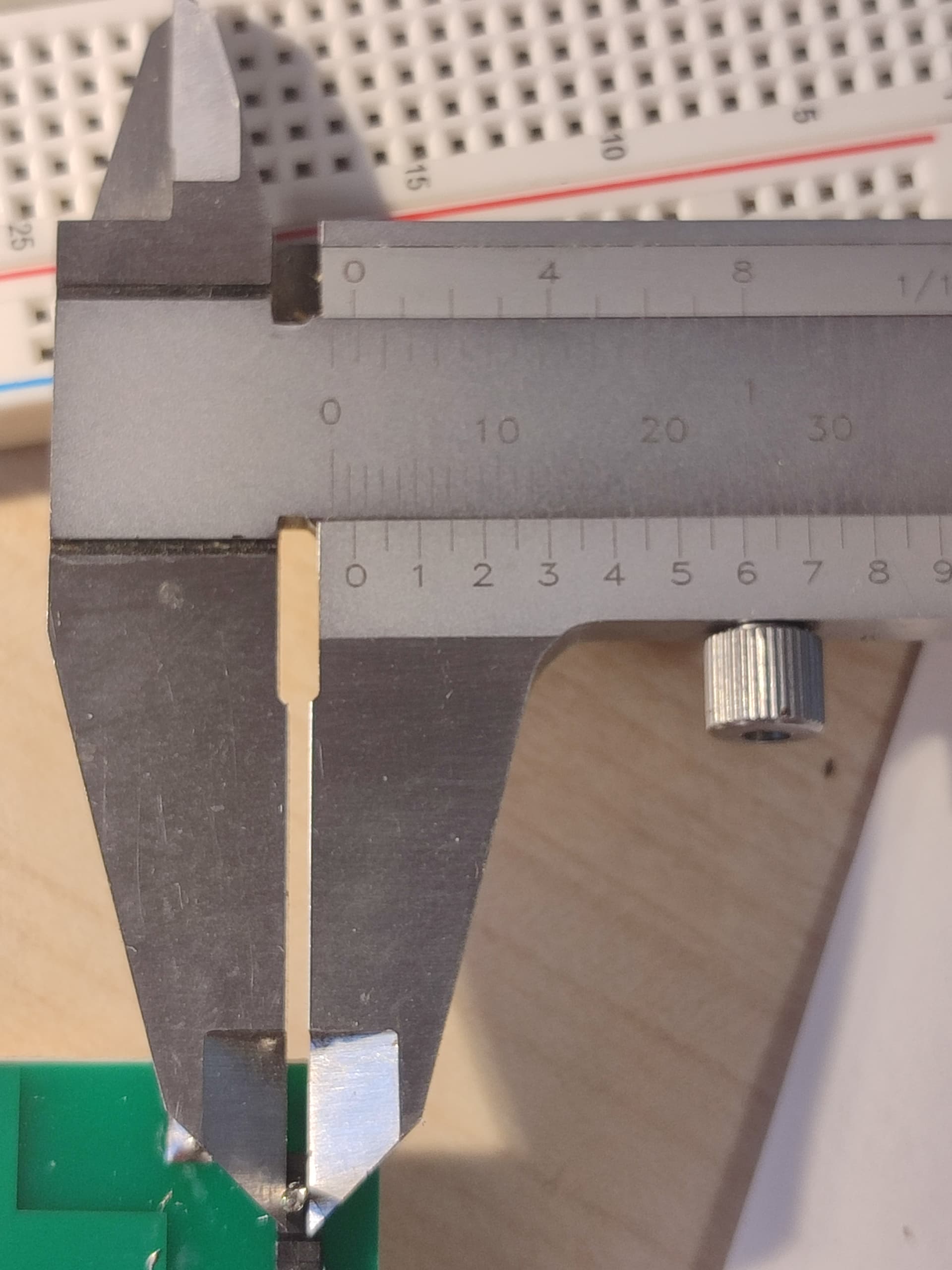
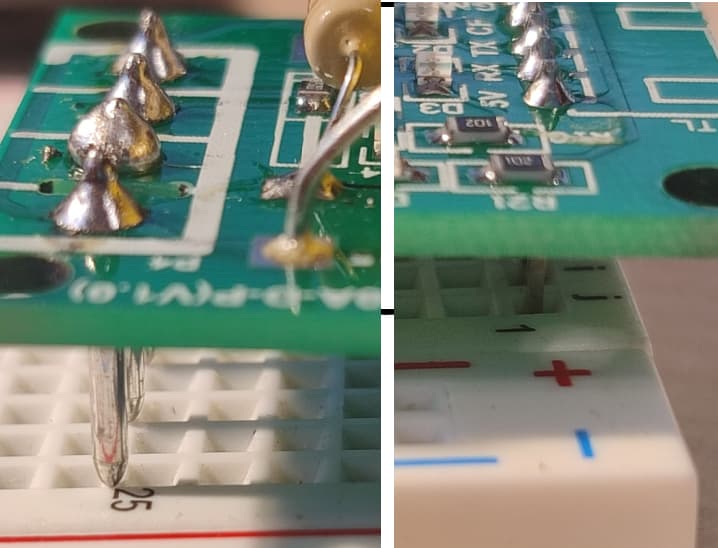
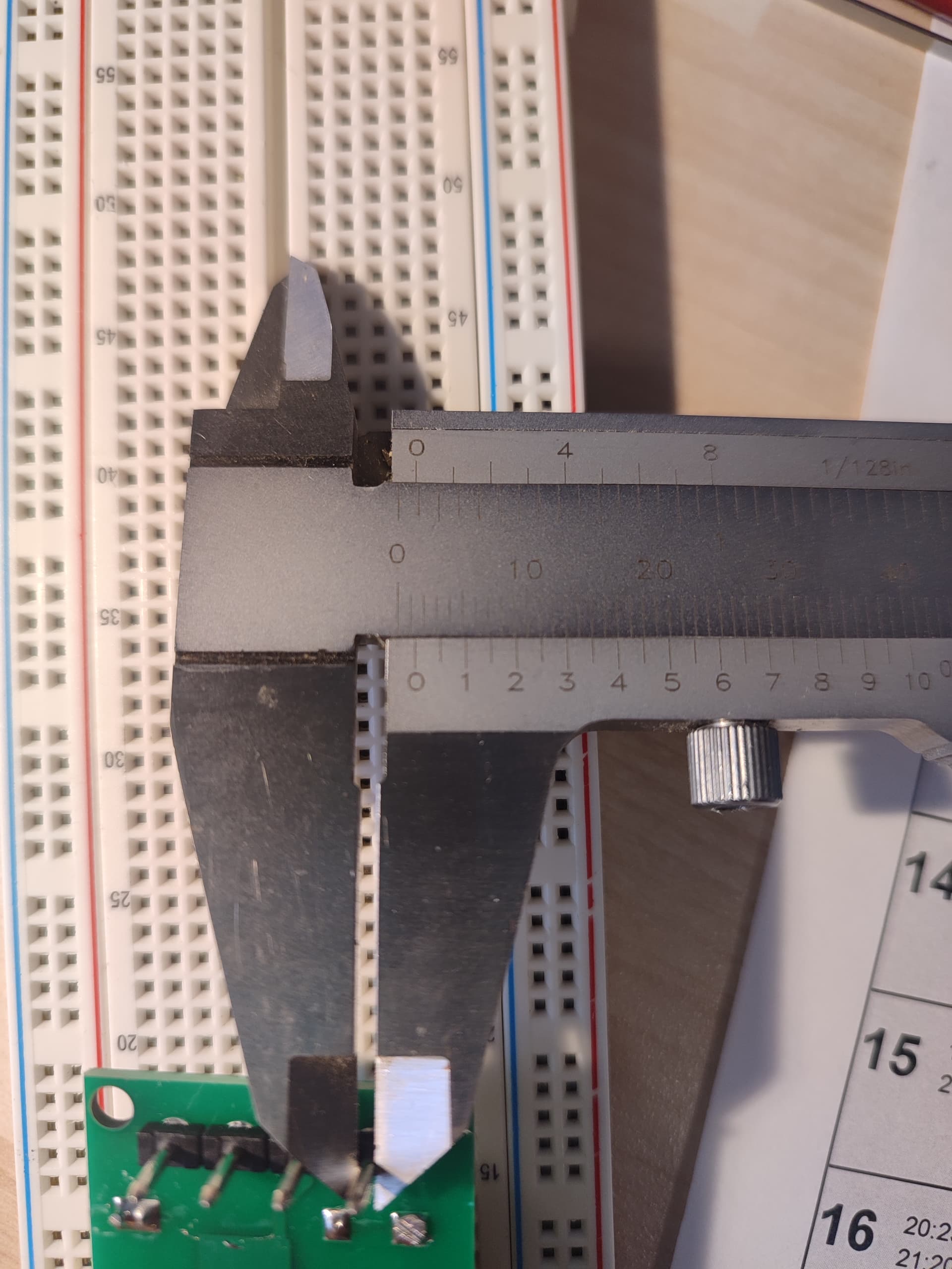
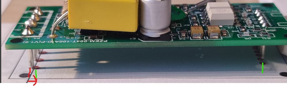
For the AC pins on the left we need to know the pitch of the pins (it appears to be 0.2in, assuming the communications header is a 0.1in header which seems likely especially when seen connected to the breadboard in one of the images.) We also need to know the diameter of the pin to know how large the hole in the pcb needs to be (the 0.1in header is likely the standard 0.038in, the AC connectors look larger but how large is not indicated and unknown.) One of the flat images would likely allow a close enough layout but we need the diameter of the AC connectors to do much and it isn’t here. This is also a dangerous thing to use as 120 / 230V is available on the pcb which is potentially life threatening if not properly protected. If you have a board and digital calipers you should be able to measure the pitch (the spacing between pins) and the diameter of both sets of pins. Otherwise you would need to ask the vendor what the size of the pins is very likely.
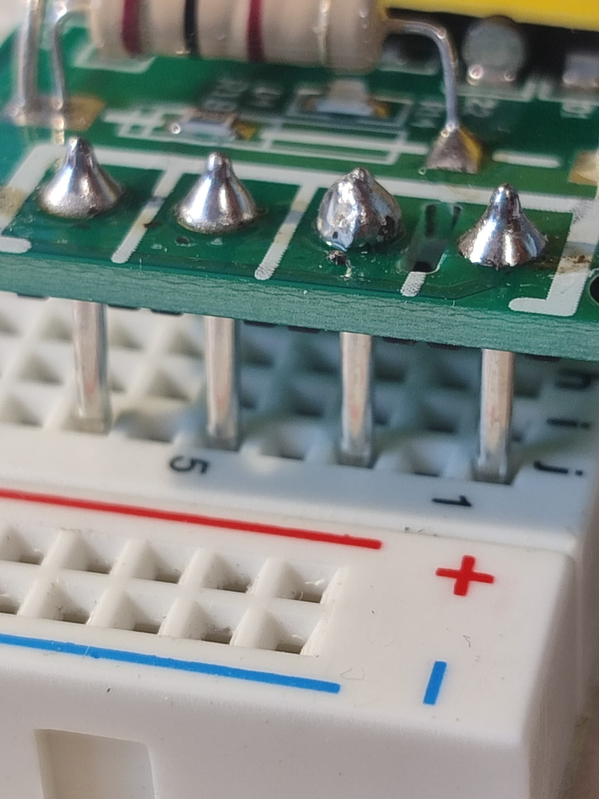
The only remaining question is what is the size (in in or mm) of the AC pin? I can’t tell from the photo of the calipers. The pitch is indeed 0.1in so if we know the diameter of the AC pins (which looks to be larger than the header on the other end of the board in the photos which may or may not be true!) that should be enough to make a part.
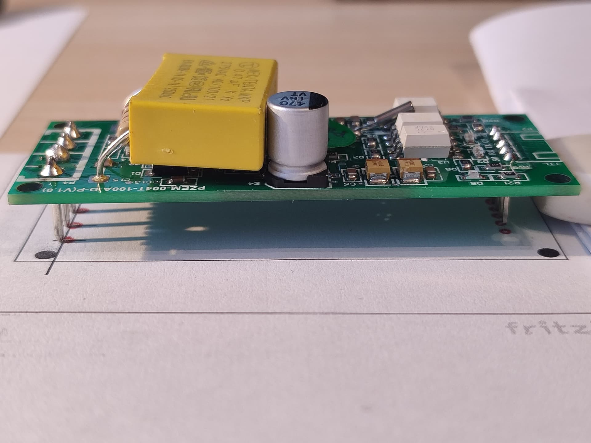
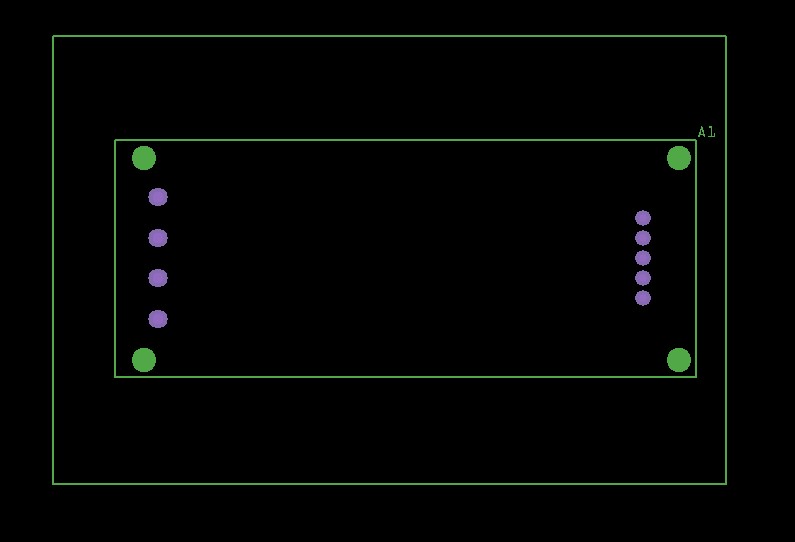
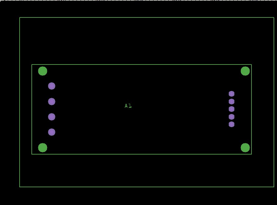
This part may do what you want. Pcb may be a little off as it was made from the jpeg images. You should print the pcb footprint out at 1:1 scale and compare it to the board and see if the pins align correctly. The holes for the power pins are drilled at 0.055in, the pins appear to be 0.045in but checking the pins will fit in a 0.055in hole would also be a good bet.
edit: Modify the position of the AC connectors to be a little further left. Note if you have already loaded the part you will need to remove the part from your mine parts bin then shutdown Fritzing answering yes to the keep part and keep parts bin prompts (you can answer no to the save sketch prompt) then restart Fritzing before it will let you load the new part.