Pulse Sensor Amped!

Hi Y’all,

We love Fritzing over here at World Famous Electronics, and we’ve finally gotten around to making our part in your format :stuck_out_tongue:
Pulse Sensor.fzpz (8.0 KB)
We also host the .fzp and .svg files on our github here
You will soon see Fritzing diagrams on our tutorials and such at pulsesensor.com

Not bad, but a few problems: breadboard and schematic lack group breadboard and schematic respectively. The only thing I know that does is make svg export of your part not work. Schematic is scaled a bit wrong (I’m not sure why as the svg looked fine and is defined in mm) but it was missing the connector terminal ids which means that the lines in schematic terminated in the center of the pin rather than the end as they should. The following sketch has a corrected part in it (which you can extract by exporting it from the temp parts bin as an fzpz file). I didn’t make a new part, so your original and this one won’t co exist (fritzing will tell you the part is already loaded) but if you make the same sketch with your original part you will see the problem in schematic.

Pulse_sensor-fized.fzz (11.0 KB)

Peter

Hey, thanks for fixing it! Though I’m not quite sure what the issues were… I’m new to designing in your system.
I downloaded your .fzz, and then exported the part. Then I removed my other part, and rebooted Fritzing. After restarting the software I imported the .fpzp based on your changes. The only issue that I see in the Breadboard view is that the Pulse Sensor ‘pins’ are not lined up with the breadboard holes. I had to change the grid to 0.05" spacing to get it to work.

I notice that there is some metadata that I need to edit, Then I will upload the new .fpzp

Here is the updated Pulse Sensor Part. Please let me know if it is ready for prime time.
Pulse Sensor.fzpz (8.0 KB)

Nope still appears to have both problems. Let me try and make them clearer:

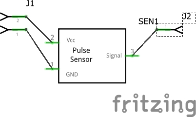
This is the lack of terminalids on schematic. It manifests as the line connecting to the center of the pin definition like this in both your parts (where j1 and j2 are a 2 pin and 1 pin header connector from core parts):

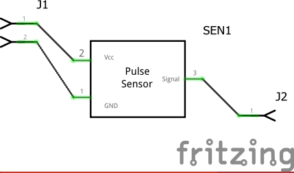
what you want is this (from my new version):

which is produced by changing this in the schematic svg:

   <path
      gorn="0.3.0.0.5"
      d="M 7.0965554,332.20642 0,332.20642"
      stroke="#696969"
      stroke-opacity="1"
      stroke-width="0.64"
      id="connector1pin"
      fill="#696969"
      fill-rule="evenodd"
      stroke-linecap="butt"
      stroke-linejoin="miter"
    />
    <path
      gorn="0.3.0.0.6"
      d="M 7.0965554,346.63323 0,346.63323"
      stroke="#696969"
      stroke-opacity="1"
      stroke-width="0.64"
      id="connector0pin"
      fill="#696969"
      fill-rule="evenodd"
      stroke-linecap="butt"
      stroke-linejoin="miter"
    />

to this:

   <path
      stroke-opacity="1"
      stroke-linejoin="miter"
      stroke-linecap="butt"
      stroke-width="0.63999999"
      stroke="#696969"
      fill-rule="evenodd"
      fill="#696969"
      gorn="0.3.0.0.5"
      d="M 7.0965554,332.20642 H 0"
      id="connector1pin"
    />
    <rect
      stroke-width="0"
      fill="none"
      height="0.69999856"
      x="3.5527137e-015"
      gorn="0.1.29"
      width="0.72000015"
      y="331.8197"
      id="connector1terminal"
    />
    <path
      stroke-opacity="1"
      stroke-linejoin="miter"
      stroke-linecap="butt"
      stroke-width="0.63999999"
      stroke="#696969"
      fill-rule="evenodd"
      fill="#696969"
      gorn="0.3.0.0.6"
      d="M 7.0965554,346.63323 H 0"
      id="connector0pin"
    />
    <rect
      stroke-width="0"
      fill="none"
      id="connector0terminal"
      y="346.2197"
      width="0.72000015"
      gorn="0.1.29"
      x="3.5527137e-015"
      height="0.69999856"
    />

which adds a .01 inch rectangle as the terminalid which is centered on the end of the pin where the line connects (as noted without it, the connection defaults to the center of the pin so .05 in from where it should be). Then you need to set the layer id to schematic by making a group of the entire image and naming the resulting group schematic. As noted all lacking this breaks is exporting the sketch as an svg (the part will be missing).

  <desc
       id="desc3">  
       <referenceFile>Pulse_Sensor_c124af3144d0973be29c3879c68bd19a_2_schematic.svg</referenceFile>
  <g   
    transform="translate(0,-324.1879)">
    <g>
      <g
        gorn="0.3.0.0"

to:

  <desc
    id="desc3">
    <referenceFile>svg.schematic.Pulse_Sensor_c124af3144d0973be29c3879c68bd19a_2_schematic.svg</referenceFile>
  </desc>
  <g
    transform="translate(0,-324.26784)"
    id="schematic">
    <g

so the top group has the id schematic as the layerid. The same needs to happen in breadboard (I did a select all and then created a new group because there wasn’t an enclosing group) with the layerid breadboard.

Peter

As an alternative to editing the XML to move the connection points you can also open the part in the parts editor and move them there. To move them in the editor you can grab the center of the cross hairs and move it but that can be difficult because it wants you to keep the mouse over the hair exactly. The next option would be to click on the connection and then change the coordinates in the pane on the right. But my favorite option is to click on the connection and then click on the direction in the pane on the right (Center, West, North, East, South). No complicated easy to mess up XML editing at all.

Hello again,

OK, I made the changes, and I think I got it right this time :slight_smile: Don’t want to smile too soon…

Pulse Sensor.fzpz (8.2 KB)

Yep this one looks fine. Everything appears to be correct.

Peter

Hey, I updated the breadboard and icon svg files. Just want to run this by you.
Pulse Sensor.fzpz (8.8 KB)

You can also find this at https://github.com/WorldFamousElectronics/Fritzing_PulseSensor_Files

Some problems: breadboard lacked the breadboard view layer id (all that breaks is svg export of the part), the fzp file had both terminalId and legId so I removed the legIds (only needed for bendable legs which this part isn;t) and the pins aren’t on .1 inch centers (I didn’t correct them as they are fairly close). Schematic had lost the labels for connector0terminal and connector1terminal and needed a edit->select all and resize page to document in order to get the pin alignment to .1 centers. Corrected in this part:

Pulse Sensor_3.fzpz (9.4 KB)

Peter

Thank you Peter! Really appreciate your help. I will update my files and github.

Not a problem,. as usual I discovered another oversight (I needed to add a warning about not defining both a terminalId and legId in a fzp file to my python script that checks parts) so we all win. With the additional test it sees these problems with your original part:

Error x7: File
’…/imported_parts/Pulse Sensor_3/part.Pulse_Sensor_9b42ac4ae84eebb2bab0e9098e88835f_5.fzp’
At line 52

Both terminalId and legId present, only one or the other is allowed.

Error x7: File
’…/imported_parts/Pulse Sensor_3/part.Pulse_Sensor_9b42ac4ae84eebb2bab0e9098e88835f_5.fzp’
At line 67

Both terminalId and legId present, only one or the other is allowed.

Error x7: File
’…/imported_parts/Pulse Sensor_3/part.Pulse_Sensor_9b42ac4ae84eebb2bab0e9098e88835f_5.fzp’
At line 82

Both terminalId and legId present, only one or the other is allowed.

Error 18: File
’…/imported_parts/Pulse Sensor_3/svg.breadboard.Pulse_Sensor_9b42ac4ae84eebb2bab0e9098e88835f_5_breadboard.svg’

Connector connector0leg is in the fzp file but not the svg file. (typo?)

Error 18: File
’…/imported_parts/Pulse Sensor_3/svg.breadboard.Pulse_Sensor_9b42ac4ae84eebb2bab0e9098e88835f_5_breadboard.svg’

Connector connector1leg is in the fzp file but not the svg file. (typo?)

Error 18: File
’…/imported_parts/Pulse Sensor_3/svg.breadboard.Pulse_Sensor_9b42ac4ae84eebb2bab0e9098e88835f_5_breadboard.svg’

Connector connector2leg is in the fzp file but not the svg file. (typo?)

Error 18: File
’…/imported_parts/Pulse Sensor_3/svg.schematic.Pulse_Sensor_9b42ac4ae84eebb2bab0e9098e88835f_5_schematic.svg’

Connector connector0terminal is in the fzp file but not the svg file. (typo?)

Error 18: File
’…/imported_parts/Pulse Sensor_3/svg.schematic.Pulse_Sensor_9b42ac4ae84eebb2bab0e9098e88835f_5_schematic.svg’

Connector connector1terminal is in the fzp file but not the svg file. (typo?)

Peter

Hi Peter,

OK, so does it matter which I select, terminalId or legId?

I’m not sure I understand the error about the connector legs being in the fzp but not the svg… Can you clarify?

Joel

You want terminalId, legId is used when you have bendable legs (and they are a fair bit more complex to configure).

The script reads the fzp file which defines all the connectors and layers and svgs, then it reads the associated svgs and checks that the connectors specified in the fzp file actually exist in the svg file. In this case its saying that the legId is defined in the fzp file (which it is) as being part of the breadboard svg, but the connector isn’t defined in the breadboard svg (which is also true). What you want to do is remove the legId from the fpz file as it shouldn’t be there.

Peter