Hi,
I use a PS2 gamepad controller in mi projects and It would be great I could use it in the fritzing protoboard window (schematics and pcb are not necessary).
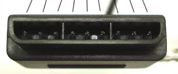
I would only need the 9-pin connector port:
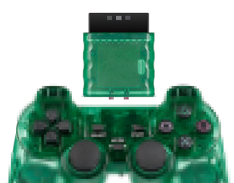
And it looks like this:
Thanks in advance!
Hi,
I use a PS2 gamepad controller in mi projects and It would be great I could use it in the fritzing protoboard window (schematics and pcb are not necessary).
I would only need the 9-pin connector port:
And it looks like this:
Thanks in advance!
The Fritzing gods have smiled on you  , some skilled person has posted a svg of the ps2 gamepad under the creative commons licence so I swiped it. There is a female connector available (but no layout information) available from Robotshop here
So this is a full part (bb schematic and pcb) but pcb is likely wrong as the positions were done from a rescaled jpg image. If someone has one of these connectors and will post the size and position of the pins I’ll fix pcb up.
ps2-gamepad.fzpz (11.0 KB)
Peter
Hey there @vanepp,
I’m building my own USB to PS1/2 controller adapter, and can confirm the spacing on this part is a little bit off. The main connector pins are actually 4mm apart - the closest equivalent in Fritzing seems to be “0.156in (3.96mm)”, I’ve had a little breakout board made up to test and this spacing works exactly with this connector. The pins seem to fit through 1mm holes.
The extra pin for grounding the cable’s shielding is also about 5mm away from the middle pin on the connector, and (at least on the one I’ve bought) has a rectangular cross-section, about 1.3mm wide and 0.35mm thick (source: my digital calipers). This pin might vary from connector to connector, and when bent slightly so it’s perfectly straight and parallel is closer to 5.5mm away, so a 1.5mm hole might be best for this one.
If you’re still around and willing to update your Fritzing part with the above information, I’d happily get another breakout board made and verify its correctness.
For anyone else stumbling on this in the meantime: Create a generic 9-pin header with 0.156" (3.96mm) pin spacing, with the default 1mm holes, and place it on the edge of your board - that should be the exact sizing and spacing to solder in a Playstation controller socket.
Currently the pitch looks to be 3.835mm (probably a scale issue with the jpg I got it from) I will correct them to 4mm pitch. The holes are currently 0.038in (the size for a 0.1in header) 1mm would be around 0.040 (0.03937 actually) if the pins are tight in the current holes I can change the hole size up. The other hole is currently about 1.7mm (0.070in) so I’ll reduce it in size a bit and move it down.
OK here is a corrected part with the pads on 4mm pitch (but still on 0.038in holes!) and the extra pad set 5MM offset from the pins and 0.06in hole (1.5mm approx.) If you print out the pcb footprint at 1:1 scale from Fritzing (possibly on transparent overhead paper) you should be able to compare it to a real part without ordering boards.
ps2-gamepad2.fzpz (11.0 KB)
If this part checks out I will replace the original one! Thanks for the update!
edit:
Looking at the pcb footprint I see I moved the connector outline but didn’t move the square so providing corrections for that would be appreciated!
Peter
from two posts above is the corrected part. The OP never replied with a check that it is right so I never replaced it.
Peter
woww, i checked your github and the tank looks amazing !! is this project completed ?
Sorry I haven’t responded - a lot’s gone on since I started this thread. I did have a prototype breakout board made with that footprint but don’t think I got around to properly testing it. I will come back around to this at some point.
I’m pretty sure Theas1995 is an LLM bot - suddenly showing up and responding to old posts, replying to the wrong person for the details given, generally the whole thing doesn’t ring right.
ahh i do hope that this project is a success!i look forward to the completed project.
also yeah theas does sound like an ai replying lol
