Project: DIY Smart Watch with Multiple Functions (Prototype in Development) THESIS for University

Hello everyone,

I’m completely new to Arduino, electronics, and PCB design, but I’m very excited to pursue a personal project. I’m trying to develop a smartwatch that combines various features and electronic modules, all in a compact and functional design, similar to a commercial watch.

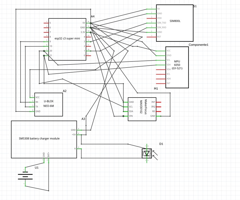
Components I want to integrate:
ESP32-C3 Super Mini – main microcontroller with WiFi and Bluetooth

SIM800L – GSM module for communication

MPU6050 (GY-521) – acceleration and gyroscope sensor

NEO-6M GPS – positioning module

MAX30102 – heart rate and blood oxygen sensor

TP4056 – Li-ion battery charging module

Small solar panel – for energy assistance

Rechargeable Li-ion battery

Physical SOS button

On/Off button

4-pin JST connector – to connect the MAX30102 sensor separately from the main PCB, and better position it in contact with the skin

Main difficulty:
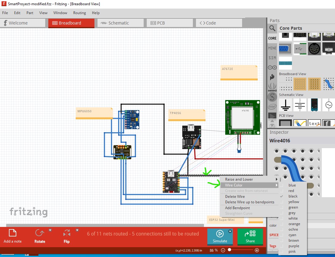
When trying to assemble everything on a breadboard or in separate modules, the final design ends up too large to fit into a wristwatch case (my goal is to keep it around 35mm x 40mm). That’s why I thought about designing a custom, double-sided PCB that integrates almost everything except the MAX30102 sensor, which I want to use via a cable.

What I need:
To know if it’s possible to design a single PCB that integrates all of these components (or at least most of them) in a small footprint.

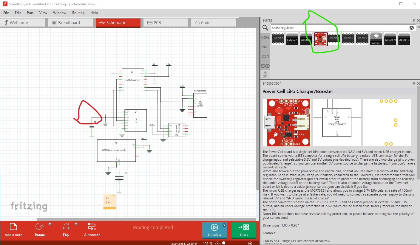
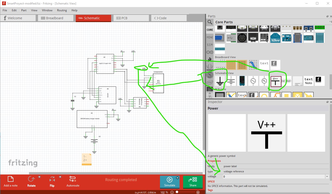
What tools would be best for this (I started with Fritzing, but I don’t know if it’s enough).

Any suggestions, examples, step-by-step guides, or experiences from someone who has done something similar?

Even if there is a company or service that can help design or manufacture something like this, it would be very helpful.

I’m learning everything from scratch, but I’m very committed to bringing this project to fruition. Any help, recommendations, or constructive criticism is more than welcome.

Thanks for reading!

I think this will be your main challenge, the Sim800l module alone takes up most of that space, it is 27mm by 39mm. Some space could be saved by putting the parts on the board, but the Sim800L module itself is 16mm x 18mm and I think there is a SIM card connector on the bottom of the board. and a RF connector needed which will add to the complexity (and skill level!) needed for success, so the breakout board, if at all possible (because it works now) is the best bet. The NEO-6M module is 16mm x 12mm (chip only without the associated circuitry. I don’t remember if it has an internal antenna on the chip or it that is external.) Again you would be best to use the module as it is likely to be complex to get a working part if you try and build your own. The ESP32-C3 Super Mini part is available SMD (and thus can be soldered to the board) that is 23mm x 18mm I would use that as is as it is easiest, you maybe could save some space by doing your own, but it is likely to be complex. Its antenna needs to have no traces running through it though which limits your trace routing. Depending on how much height you can tolerate you may be able to use 2 pcbs (one on top of the other connected via headers) to fit everything in. Getting the GPS antenna clear of everything else (especially with the GSM module which may interfere with it) may be exciting. I would probably start with the various modules in a breadboard setup as you appear to have but wired together by wires (so you can move them around relative to each other to see if they interfere with each other, and if so, if you can find a configuration that will work in the space you have.) There are a fair amount of challenges to doing this especially with several different kinds of RF modules in the mix but it may be possible. A google search, if you can figure out a good search term would likely be your best bet for finding posts on similar projects, I don’t know of one in the Fritzing forum although there may be one I haven’t seen. Something like “smartwatch with GPS, GSM heart rate monitor” although that comes up with existing smart watches as ads and no results for the search, so it doesn’t look like there are projects (although a better search term may find something!)

Peter

Thanks a lot for your detailed response — it really helped me understand the physical limitations of this kind of project.

I was wondering if you’d be open to helping me a bit further. Since I’m quite new to electronics and PCB design, I’d love to know if it would be possible for you to assist or guide me in designing the full architecture and PCB layout for the smartwatch I’m building.

I already have a clear list of the modules I want to use (ESP32-C3 Super Mini, SIM800L, NEO-6M GPS, MAX30102, TP4056, LiPo battery, and a few buttons), and I understand that space is extremely tight. I’m also considering a dual-layer PCB or using stacked PCBs if necessary.

I’m really trying to learn as I go, but having guidance from someone experienced would help me avoid big mistakes and move forward more confidently.

Sure although I’m not all that familiar with all the parts involved (I haven’t used most of them, but I have made Fritzing parts for them.) As I said the thing I would do is see how much interference the GSM module causes. It is a transmitter (as is the ESP32) and may affect the other receivers (for wireless in the ESP32 and GPS in the NEO-6M) so the place I would start is make a test bed that can run all of them at once and see if they interfere with each other. If they do and you can’t cure that by moving them around that may doom your project and that would be a good thing to find out quickly.

Peter

Thanks a lot for your reply.

I’ll try to make the test setup as best as I can, although I must admit I still have limited knowledge when it comes to wiring everything properly and running these kinds of tests. But I’m doing my best to learn.

Once I have everything connected and I’ve done some testing or research, I’ll definitely share the results with you to see what issues might come up.

I really appreciate your guidance — it means a lot as I try to move forward with this.

Best regards, Giovanni.

I’m thinking your best bet is likely to not try and shrink the final unit down to watch size and just use the breakout boards. You could mount them in a plastic box (not metal because the rf will be blocked by metal!) that attaches to a belt or strap (as I assume someone is intended to wear this device.) I would likely discard the solar cell as well and arrange a possibly larger capacity battery and an external charger from an external power source. The only potential down side to this is the MAX30102. As I recall it is analog output and the length of the wires between it and the box may introduce noise in the signal. I expect this has the greatest chance of working well. Oh, you likely also need a boost switching regulator to boost the 3.7 - 4.2V LiPo battery to regulated 5V for the boards as well. Most of the boards will expect regulated power not a battery (I think the ESP may be capable of taking input from a battery, but it probably won’t provide sufficient current at 5V to drive all the other boards!) Hope this helps!

Peter

Thank you so much for your valuable advice; it’s really helpful and I appreciate it.

I’ve been looking for ways to improve the size and integration of the project, and based on that, I’ve replaced the GPS and GSM modules with a single SIMCom A7672E board. It supports 4G LTE Cat-1 and GNSS, so it seems like a more space-saving option for a wearable device. I’m still in the early stages of testing, but I hope this will simplify things a bit.
The board doesn’t appear to be available in Fritzing.
For the case, I’m thinking of using a 3D-printed one or a plastic case to avoid RF issues; as you mentioned, metal would interfere with the signal. I plan to place the MAX30102 and MPU6050 on the wrist side of the case to improve contact and hopefully get more accurate readings. As for power, I’m considering removing the small solar panel (or perhaps leaving it as a secondary source) and instead installing a larger capacity LiPo battery and some sort of external charger. I’m also investigating whether I’ll need a boost converter to ensure a stable 5V voltage for the modules, as I’ve read that some components might not work well directly with battery voltage.
What are your thoughts on this change and the rest?
There’s still a lot to learn and test, but your feedback has been invaluable in helping me make these decisions. Thanks again!

There doesn’t appear to be a friting part for this board. If you have a web site with physical dimensions and connector information I can make one. Your other suggestions sound fine, you are going to have the best idea of what you need and can tolerate but we can give advise on problems we foresee.

Peter

A7672X This is the page I found about the module, if I find anything else I will pass it on.

On aliexpress to buy, I found it like this

That appears to be just the chip. I expect you want a breakout board like this one (which is reasonably compact)

It appears to be only GSM no GPS that I can see though.

Peter

This one I found I think has both, GSM AND GPS

Yes that appears to have both. I don’t think there is a Fritzing part for it yet, but I can make one easily enough if that is what you decide to use.

Peter

Yes, please. Once it’s finished, I’ll add it to the schematic and then send a picture of how it looks. After that, I’ll start doing some tests. If everything goes well, I’ll buy the materials to put it all together. Thank you very much!

Giovanni

OK this part should do what you want. Note they sell both a gps and non gps version it appears (the difference appears to be 2 external antennas for the gps model and only one antenna for the non gps model.) As well by default the mounting holes are not drilled by default in pcb, if you want mounting holes you need to drag the pcb->hole part in to your sketch, place it over the hole in silkscreen and set the size appropriately in Inspector.

A7672E-board.fzpz (16.1 KB)

Peter

I’ll keep that in mind, thank you very much. I’ll start working on this right away and let you know how it goes.

This is an update on what I’m working on. I’d love to hear what you’d add. If you could download it and review it a bit, I’d appreciate it. Once it’s ready, I’ll start running all the tests and ordering the materials. Thanks so much for your help, Peter!

Giovanni

SmartProyect.fzz (73.9 KB)

Looks mostly OK, a few issues though. I cleaned up schematic a bit by adding ground and power nets to reduce clutter

You may want to find an equivalent (as Sparkfun no longer appears to sell this one, I assume it has been retired) combination LiPo charger/booster as otherwise you need to add a booster to get the battery voltage to 5V regulated. I assume someone else or possibly Sparkfun with a new version will have something like this with the regulator built in to the charger. The schematic ground and power net symbols are available here

As well you will need a source of 5V from an external source (not the 5V supply from the ESP32!) to charge the battery either from a USB connection or another source of 5V. The charger will try and draw current from the 5V source to charge the battery, so it can’t be supplied from the battery. Here is a copy of the sketch with the modified schematic

SmartProyect-modified.fzz (77.2 KB)

In breadboard you likely want to change the wire colors to make it easier to see where the wire goes. To do that select the wire and then right click on it and select the wire color like this

Peter