OK, a couple of things to consider. Hopefully the 12V 3A power supply is current limited to 3A, and if not you need to switch to one that is. The reason for this is that the capacitors when discharged will try and draw all the current they can get at start up, which will overload both the power supply and the current rating of the diode. If the power supply is current limited it will reduce the voltage from 12V to something lower until the output current is only 3A and the voltage will then increase to 12V as the capacitors charge. That has the effect that it will take the capacitors some small time to charge up to 12V (I’d expect under a second off the top of my head.) I would use the 5A diode so either the SR502 or SR506 would work (either easily supports the 12V in use, but 5A leaves some head room at 3A so the diode isn’t operating at its maximum rating.) The other thing you may want to do is increase the size of the traces on the board due to the somewhat large current. To do that select the trace
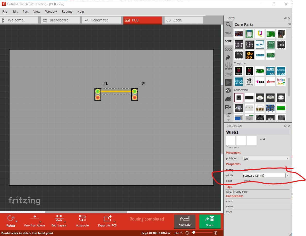
then in Inspector change the trace widh to something larger.
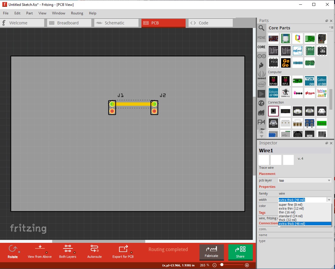
this reduces voltage drop due to resistance in the traces. In practice you can change the trace width up to as high as 999mils (almost an inch) by typing 999 in to the field (the pull down menu doesn’t go that high though.) In your case one of the pull down values should work fine, make the traces as wide as possible in the space available and there is a bug that larger traces tend to not connect to the pads correctly (although it may have been fixed in 0.9.6.) You may also need to check the current rating of the connectors. As I recall 0.1in headers have a maximum rated current of 2A, so running 3A through them may cause them to fail over time. You may need something like screw terminals which are typically available in higher current ratings (and again, you want something with a 5A current rating to leave head room at 3A.)
Peter