Not sure whether to post this as bug yet. I can’t be the only one having these problem, but maybe I am missing something.
I was asked for a circuit diagram of my Mk I Arduino robot (stroppy tech support people at supplier). This particular robot is pretty simple, so I did not have a diagram. So I bunged together a Fritzing diagram in schematic view. One of the parts needed some customization, and I had to make a huge Generic IC for the robot shield, but nothing too difficult. The problem came with the wires between the parts, which required a lot of bend points. They looked reasonably OK until I exported them as PDF. Yuck! Lots of “dog legs”, i.e. lines that are not quite horizontal or vertical. No matter how much I played with the connections and the bend points, I could not get the lines orthogonal. Snap is on and the connections snap to each other and bend points snap to the grid locations, but when you look at the results in PDF or SVG format, the lines are not level. I resorted in the end to editing the fz file in a text editor to remove the numerous small error values. Wah!!
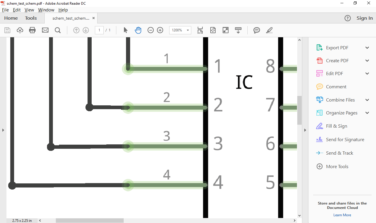
Here is a very simple Fzz to demonstrate the problem: schem_test.fzz (4.9 KB)
If you export it to PDF, depending on your settings you can clearly see the bad lines. Also if you look at the xml you can see a lot of examples like this:
Tried that. If you turn off the ‘helpful’ smoothing preferences in adobe you can see it better, but they are there either way. It’s in the FZZ file data too.
Ahh, now I see it. Yes the lines aren’t straight, they are on a slight diagonal. It’s even worse in PNG.
I checked the part and the leg spacing is exactly 0.100", so it must be that the grid in FZ is a bit out because it’s snapping a touch higher then the part or the part is snapping a touch lower. Notice that one of the traces is straight.
I think this is not so much a bug as a feature of sorts. I think the base problem is that at least Inkscape (because thats all I’ve used) doesn’t snap the objects in a group to the grid. It does (apparently whenever it feels like it) add translation and scaling I think making things even less correct. Some of the foot prints I’ve seen aren’t actually on .1 centers but rather .104576 etc (and different between pins) not enough to bother anything too much in the real world but not correct as it could be either. The solution in my head (which hasn’t yet made it out my fingers, because I’m still unscrewing my previous errors in parts creation ) is a prototype footprint editor in perl/tk that would do only the stuff needed to make footprints not all the general stuff that Inkscape supports. Tell you what the pad and hole size of this pad is, align it to the grid exactly (unless you tell it not to), Repeat this same pad .1 (or whatever) spaced horizontally or vertically. I think that is what the developers originally intended with the next version of the parts editor. Perhaps I’ll get there first, perhaps they will . As to the group, parts-help seems appropriate to me as this is likely really about the parts.
0.004" is a lot - I was a machinist -, but that’s probably just some parts because I checked this one and it’s correct to the thou/mil vertically. It looks more like the grid is out.
EDIT
I changed the grid to 0.200" then back to 0.100", and then moved the corners and put them back, and they are better.
Looking at his parts was going to be my next move after finishing correcting my parts. However the rectifier diode in core is one foot print that is out by a bit.
so the pad is misaligned .02 in X as it is .302 long not .300 as it should be. On a board it won’t make any particular difference but on a grid (depending on scale) it may. I’d expect the core parts to be the most accurate. I noticed this on the gerber view as this is one of the parts I screwed up when I changed it.
That unfortunately isn’t the only one, because to me it feels like 40% of them have something wrong. I was thinking that someone should go through all the parts and standardise them, but that could take months or a year, plus the only one with enough knowledge to get them right, in all views, the first time is Steel, so it’s probably going to be too much work.
Even simple 0.100" SCH views you see pins not on grids.
The problem doesn’t just affect the parts connections though, it creeps in to bend to bend lines too.
The parts here are code generated - we could get at least those right. For the rest, I would be more than willing to write some python or java code to go through and bulk correct the majority of the parts. and perhaps even strip out unneeded transformations. The code could check the alignment of every connector, and if the connector is by a small enough %age, correct it. Otherwise it would flag a warning. We could include a parts checking function to check for the various other gotchas.
Inside of Fritzing could we have an ‘arrange to grid’ function, that re-snaps all the parts and bends to the grid?
Going forward, rather than re-inventing the wheel with our own parts editor, I feel a better approach would be for a developer like myself to get some much needed enhancements done to Inkscape. My custom parts are a little over the top, and I like having Inkscape’s feature set. What is missing is a) a usable scripting engine / extension architecture in Inkscape (current efforts all fall far short somewhere) b) a plug-in or scripts for Inkscape using that architecture to automate most of what we do for parts in Fritzing. We could automate the whole round trip process - Launch Is from within Fz, create / edit the SVG for the part, then save it straight back in to the part in Fz.
IIRC Inkscape currently has at three attempts at automation -
Feature where a script, invoked by the user via the Inkscape menus, written in a-n-other language (you can use almost any), is fed a temporary copy of the SVG (or creates it from scratch) and then feeds the result back to inkscape. Some libraries are available in Python and Perl (I think?) to help munching the SVG, but none of Inkscape’s functionality is available in the scripts, not even a notion of which shapes are selected. You are pretty much on your own.
DBUS based architecture allowing an external program to interact with Inkscape. Very much limited largely to Linux and I think a WIP.
Command line shell. This is two sides to the same feature. Firstly Inkscape has a long list of command line options including access to many of the editing ‘verbs’ (see 2) available within the program. The secondly you can start Inkscape in ‘shell mode’, feed it the equivalent of the command line commands via stdin, interpret the responses via stdout and feed it more commands. In theory, this has the beginnings of half of what we need. Unfortunately 1) it’s full of bugs 2) the biggest bug prevents it entering GUI mode while being driven from the shell, making it non-interactive and making most of the verbs unavailable 3) the design is one pass at a file currently, i.e. the file does not persist from one command to the next (but the bugs do) 4) we would still need generator scripts within the program, which suffer the current limitations.
I would be more than willing to help push some improvements here, including the coding. It will not be easy; unlike you guys, the Inkscape team are not open to outsiders, even those who have something to offer. In fact, they are damn right rude. Which is a real shame; it is one of my favourite products.
I was thinking maybe add a small svg program to FZ, like all you really need is square and circles and slight variations of those, but I read further and it seam you want FritzScape. Fritz coding would be hard, but Ink would be an order of magnitude worse.
Yeah I know about Ink’s rudeness when I started trying to work stuff out 14 months ago. I was converting a PDF drawing to svg and the guy kept saying, “just Ungroup it, can’t you read the bottom notifications” in an abrupt way. I did it and it didn’t work, and he got more snotty. Eventually I figured out you have to Ungroup it many times, until it reads No More Groups. So I told him he didn’t say to Ungroup it until it’s at it’s base, and then he was ok after that. Now that I have a few more posts on Ink they are ok, but even then you kind-of have to know how to manipulate people by the wording to get them to do what you want.
I was just trying to submit a simple two line fix for a bug. The help on launchpad tells you how to fork the source on lp, push the changes and then you are told you must either grant inkscape rights to your repo or invite them to become part of your org so they have rights to modify the fix if they need to. If you don’t, you are warned, you may upset the code-nazi, sorry maintainer.
In both cases, when I did this I got declines with one word email replies: “No”. Gee thanks, I go to the trouble of fixing a bug, following the procedure to the letter, and all I get is “No”. I still don’t know if the fix will actually get into the product.
I like your idea of using Inkscape as the engine, I hadn’t even thought of whether it had an api that would let me get at things. I have a perl script (mostly because I learned perl in 1991 before python existed and have tended to stay with what I know best) that will move the style commands that Inkscape likes to use, but that break bendable leads in to plain xml and removes the px (that also break fritzing) from the font commands. Doing that within Inkscape would be a lot more convenient. However (it sounds unlike you ) I’m not really a developer, I spent 20+ years as a network engineer/ security officer/ system administrator of last resort rather than developing (and started life as a hardware type ). I completely agree a script it is the best answer to fixing up the parts, as you note it can fix what is obvious and flag that which is broken but not obvious how to fix for human attention which should cut down the work load substantially. To be fair to the Inkscape developers, neither Old_Grey or I are Fritzing developers we so far haven’t heard anything of them …
The inaccuracies are everywhere for me, not just where the pins are out of alignment. My main diagram has a lot of bend point to bend point wires and they are off too. When you look a the file itself about 40% - 60% of lines have a value in x2 or y2 when it should be zero.
They only look OK in PDF and SVG if the settings (anti-aliasing etc) are set so they are not so obvious - they are still there for me if you look at the co-ordinates…
 ) is a prototype footprint editor in perl/tk that would do only the stuff needed to make footprints not all the general stuff that Inkscape supports. Tell you what the pad and hole size of this pad is, align it to the grid exactly (unless you tell it not to), Repeat this same pad .1 (or whatever) spaced horizontally or vertically. I think that is what the developers originally intended with the next version of the parts editor. Perhaps I’ll get there first, perhaps they will
  . As to the group, parts-help seems appropriate to me as this is likely really about the parts.