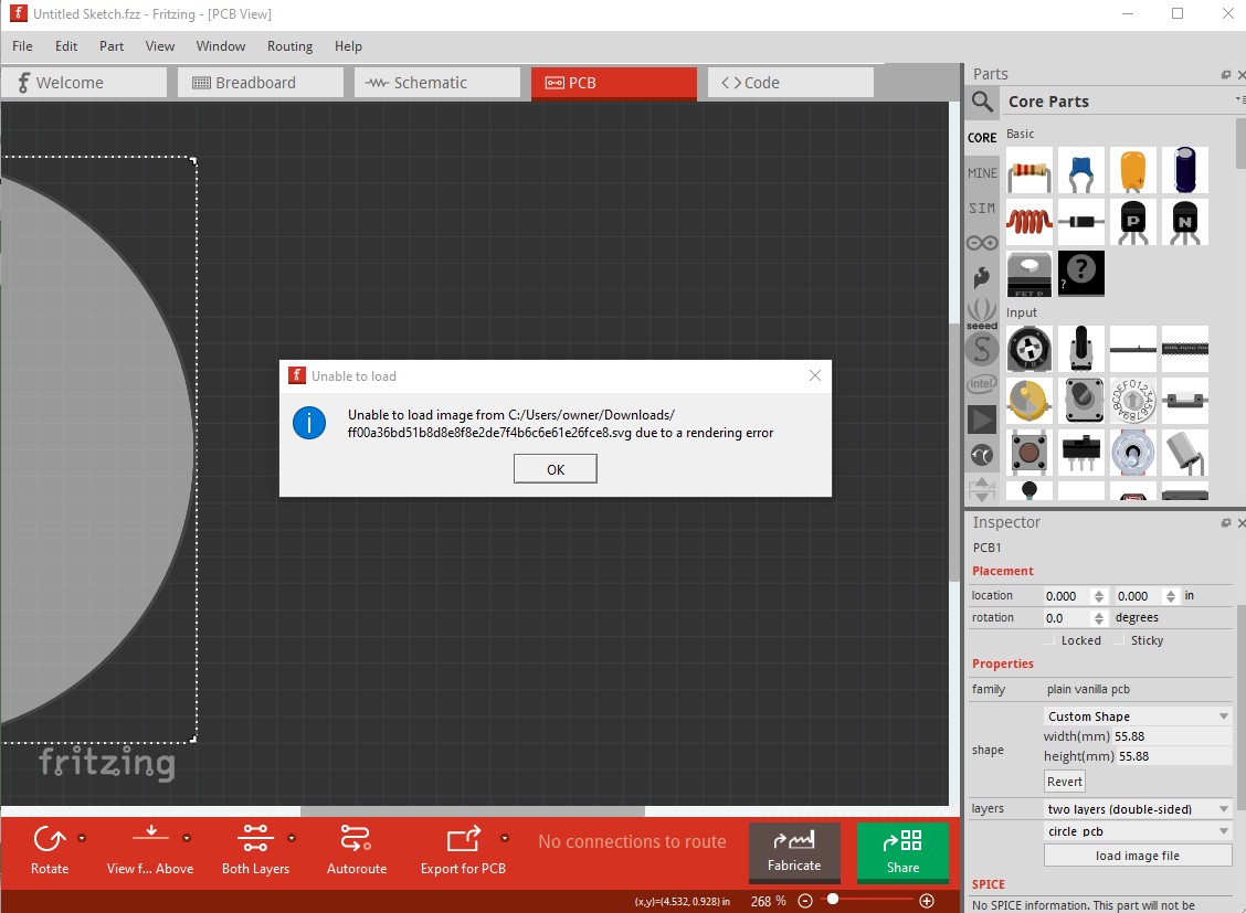
Hey all, in Illustrator I’ve made a shape for a custom PCB. I’ve tried to import it in Fritzing multiple times in different ways, but I’m constantly getting a rendering error from Fritzing.
I’ve also followed this instruction (https://fritzing.org/pcb-custom-shape/) without any succes.
Can anyone help me?
The image in Dropbox appears to be a png not an svg. The outline needs to be an svg. You can upload the svg directly here (upload is 7th icon from the left in the reply menu.) As well the svg needs to be a single differential path (can’t tell whether it is from a png file) with a specific format.
Peter
Hoi Peter!
Thanks for your quick answer! ![]() I’ve send the svg again, hope you can open it correctly. I’ve saved it as svg Tiny 1.2.
I’ve send the svg again, hope you can open it correctly. I’ve saved it as svg Tiny 1.2.

Your svg has some problems. On Fritzing 1.0.2 it doesn’t render:
that is likely because the path needs to be difference and likely isn’t. The easy solution is to only do the board outline (in the correct format) like this

(to download this, right click on the image and select save as svg.) As you see it has no holes but we can add them to the sketch like this
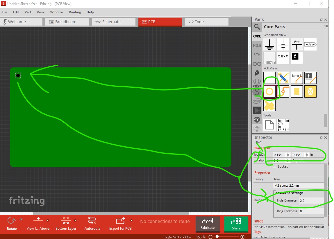
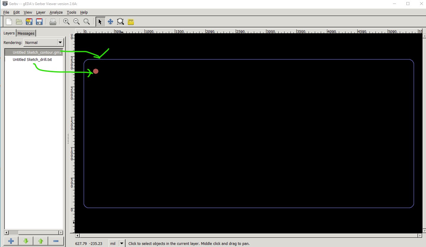
drag the hole in to the sketch then set its x/y coords and size in inspector. That produces this in the gerber output (displayed here via gerbv) where the contour.gm1 is the board outline and the hole is in the drill layer.
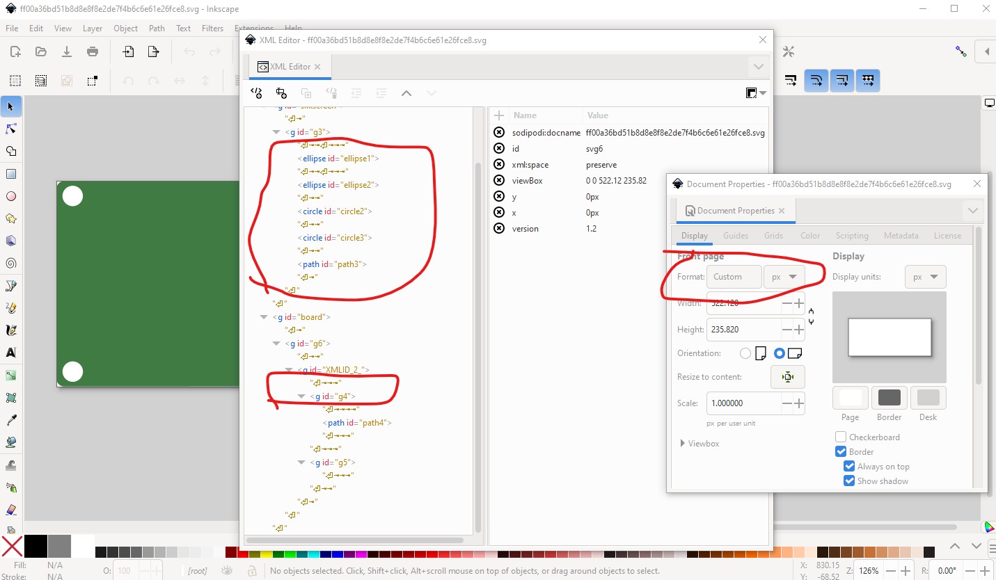
It is also possible (but at least for me a lot more difficult!) to add the holes to the path and then convert the path to difference in Inkscape which will put the holes in the contour.gm1 file. I think the holes need to be counterclockwise in the path to work correctly (I usually use path visualizer to manually create the svg with a lot of swearing) to achieve that. It is also possible if you are familiar enough with paths (which I usually am not!) to do it manually. Hope this helps! As well your original svg
has a number of problems. The path in the outline group needs to be named boardoutline and the silkscreen should be a copy of the boardoutline path with a different stroke and fill (although Fritzing is much more tolerant of changes in the silkscreen and the current one may well work.) As well the svg is dimensioned in px (and I don’t know of a way to change that in Illustrator) which will often cause problems in Fritzing as it guesses what the px to inches setting should be and often gets it wrong which will affect the scaling. It is possible that Illustrator always uses 72DPI (Inkscape is currently 96DPI which causes problems!)
Peter
Thanks Peter, for your very detailed answer!!
I’ve tried several ways, but drawing the holes in Fritzing is not a possibility because in the final version I need plenty of holes voor 3D printed parts.
After numerous attempts I’ve found the problem ànd the solution:
I’ve found 2 problems which may caused the rendering problem:
- Coloring the board. At first I just colored the board and cutted out the holes. Fritzing will not notice the holes. Painting the board-line with active paint will fix this problem, now it contains 4 holes.
- Exporting. In my export settings, the option ’responsive’ was activated. This caused the rendering error. I deactivated it and it is rendering exactly how I needed it to be!
Thank you Peter for helping me out!
