This is normal behavior. If you run the extension twice it will write a second copy of the schematic on top of the first (it will have a new group name so you can then delete the old one all at once if you like.) That is why I deleted the original svg before I started, you need to start the extension on a blank canvass.
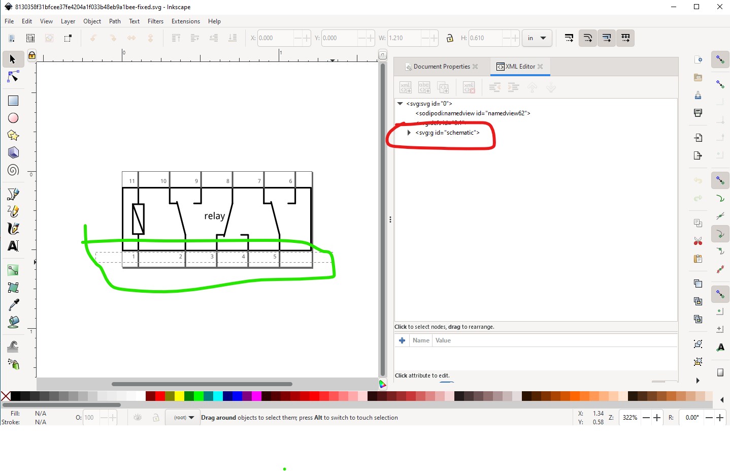
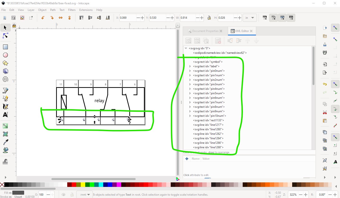
I would guess that the text was within a group. Select boxes won’t work on a group, so I usually start by doing an Edit->select all then Object->group then do multiple ungroups (usually via the keyboard) to remove all groups. Then select should work. Here the group schematic still exists so the select on the text doesn’t take when you exit the select box:
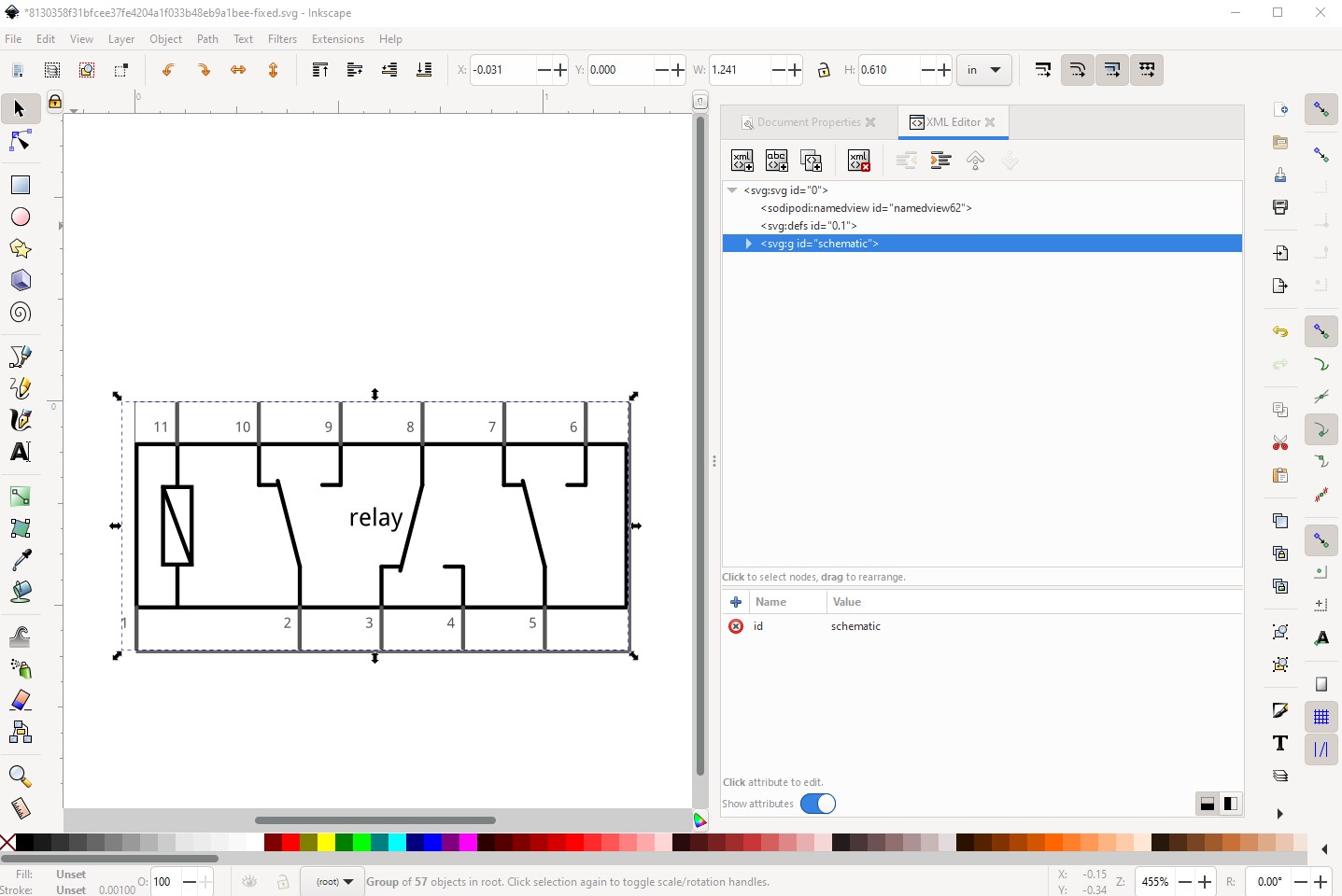
Doing a shift-cntrl-g to ungroup schematic makes the select on the text box work:
Now the delete key will delete the selected text which it wouldn’t before.
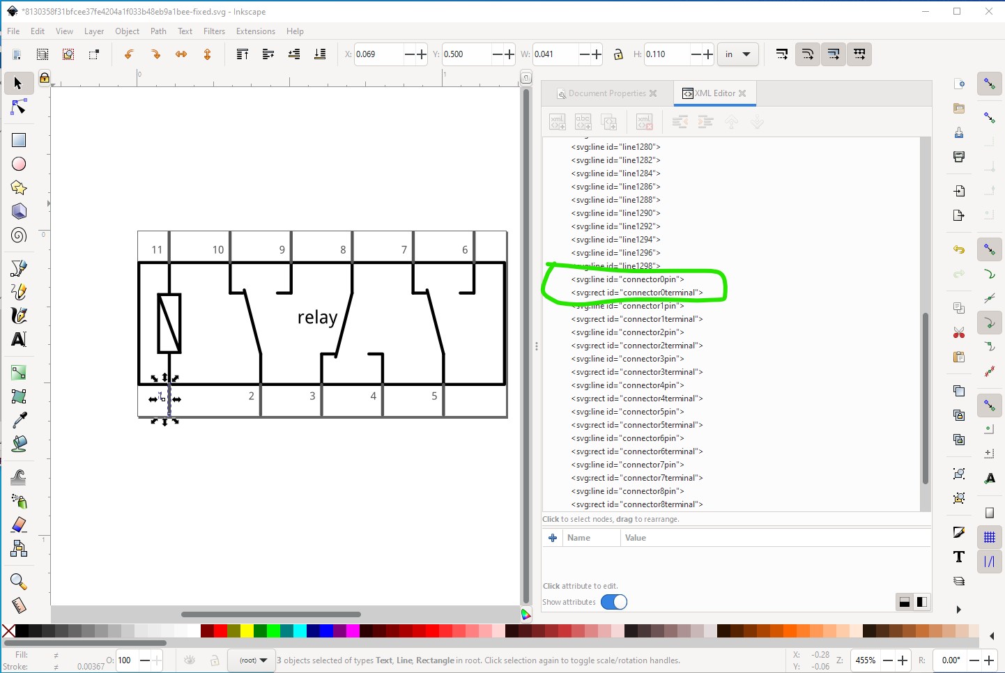
Again that is likely because it is in a group and thus won’t select with a select box. Here the group schematic still exists, and I can select the connector by clicking on the pin in xml editor and it will move, but the terminal just under it will not and in this case both the connector0pin and the connector0terminal need to move to be correct, so you need to ungroup so select will work like this. Here with the svg ungrouped, this selection will move both connector0pin and connector0terminal when the tool bar is incremented or decremented and thus keep the correct alignment.
Here both connector0pin
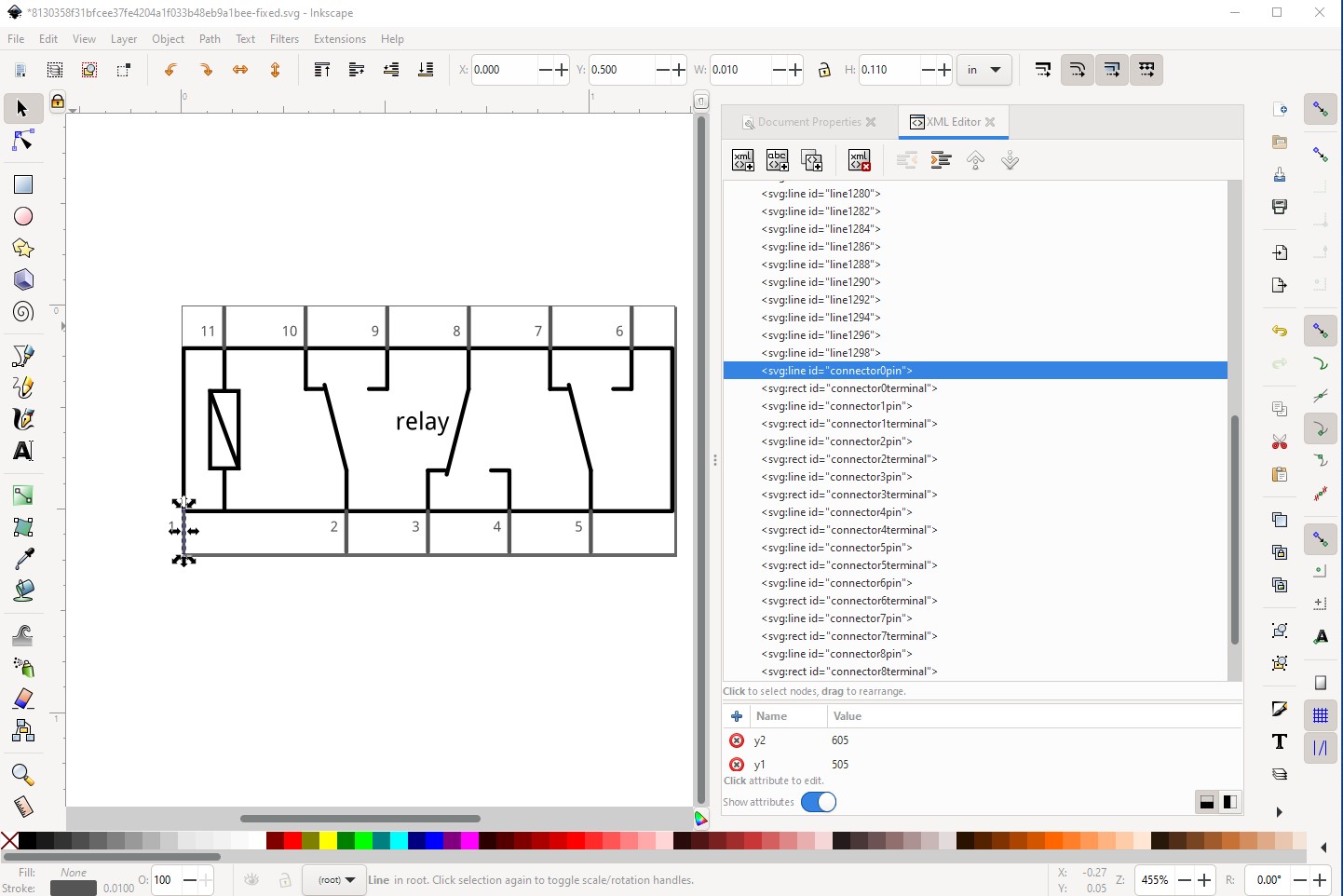
and connector0terminal (a rectangle on the bottom of connector0pin) have moved together as they should.
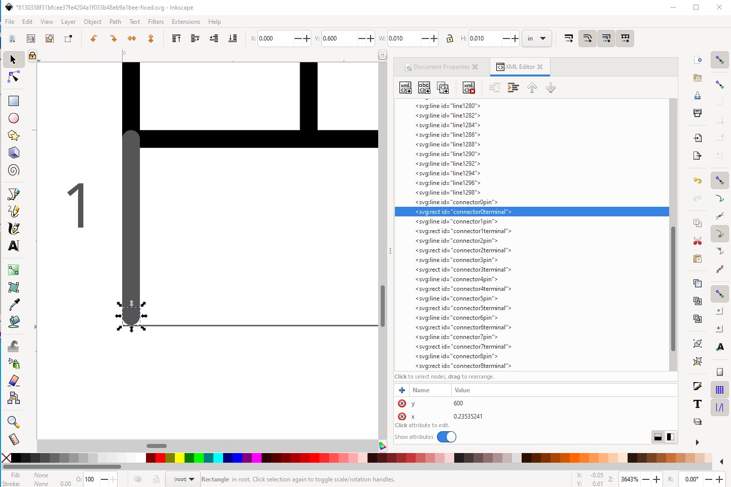
without this the terminal won’t have moved and the wire in schematic will connect to the wrong pin (it connects to connector0terminal!)
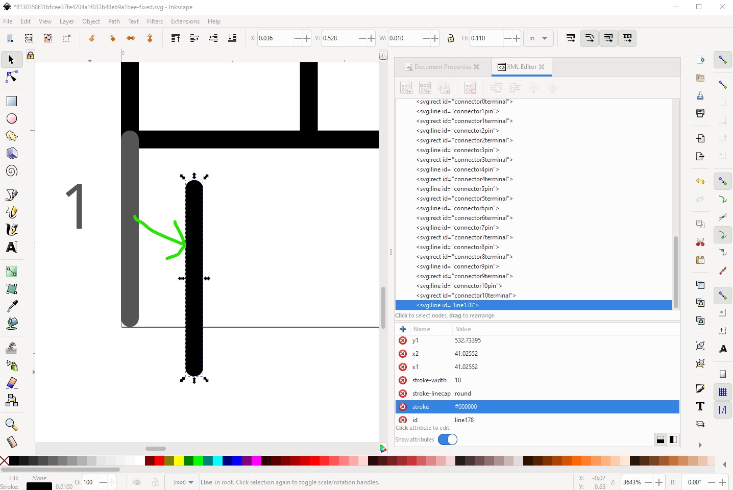
I cheated ![]() Inkscape understands but won’t create lines (lines are an Illustrator construct.) To make my interior lines I duplicated a pin like this:
Inkscape understands but won’t create lines (lines are an Illustrator construct.) To make my interior lines I duplicated a pin like this:

Then changed its color to black in xml editor and dragged it where I wanted it, then used the scale handles (or the height and width in the tool bar) to set its length.
I find this much easier than trying to draw a line in Inkscape! For the group starting from the ungrouped svg
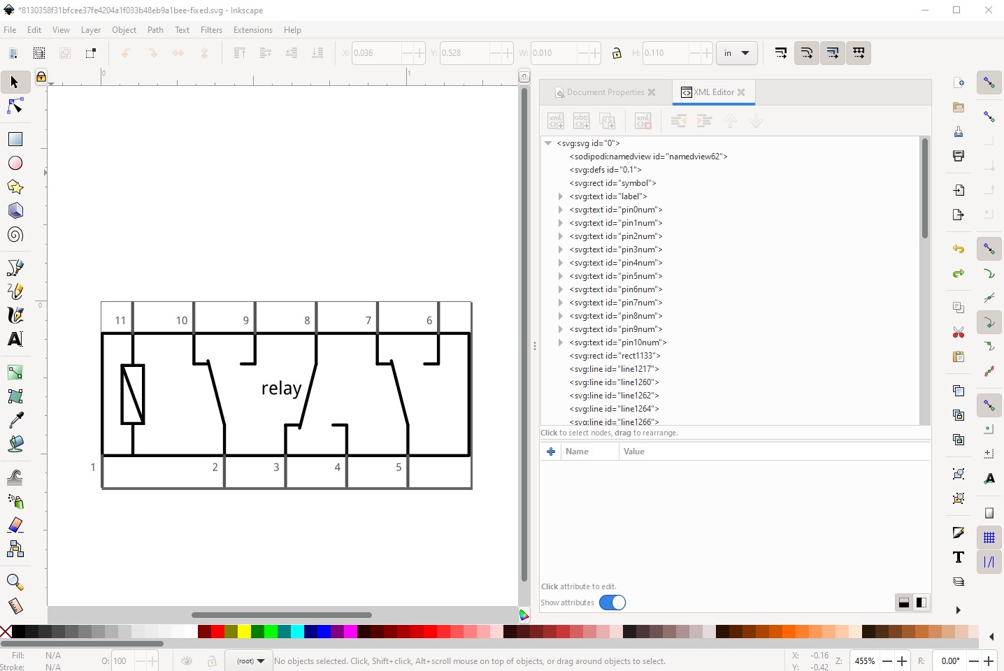
Do Edit->select all then Object->group
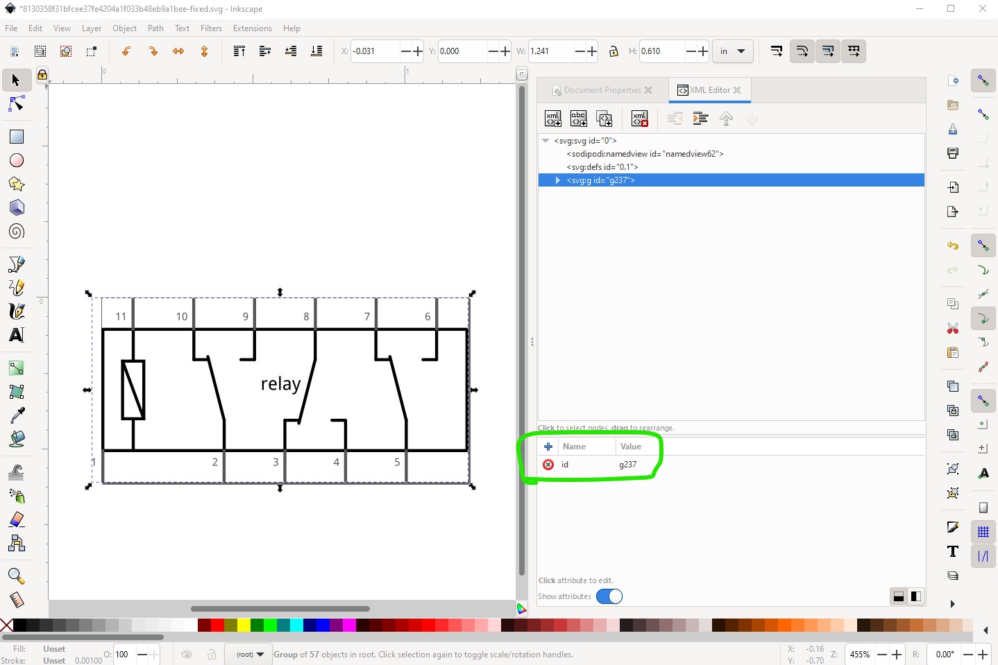
then change the group (g237 in this case) to schematic using the xml editor
You need to highlight a fritzing part and then invoke the parts editor. You can do that in either a sketch or in the parts bins. The current fzp and svg files for the part will then be loaded in to the parts editor. You can replace any of the views svg by selecting that view and clicking File->Load image for view. That will replace the current svg with the one you select (which needs to be the correct format for the view!)
Ah! This is a Fritzing quirk, the font sizes in the svg can not have px appended to them. CSS requires font-size to have a px appended so Inkscape appends them. I usually fix this by running the part of svg through FritizngCheckPart.py which among other things removes the px from font-sizes. The alternative is to edit the svg with a text editor and do a global replace of px with “” to convert this:
<text
   x="591.27441"
   y="305"
   font-family="'Droid Sans'"
   font-size="60px"
   fill="#000000"
   id="label"
   text-anchor="middle">relay</text>
<text
in to this
<text
   x="591.27441"
   y="305"
   font-family="'Droid Sans'"
   font-size="60"
   fill="#000000"
   id="label"
   text-anchor="middle">relay</text>
<text
where font-size=“60px” has changed to font-size=“60” to keep Fritzing happy. As you see there are many rules and gotchas in parts making! Inkscape is mainly for graphic artists, Fritzing use of it is non standard and takes some post processing. Hope this helps!
Peter