OK a few problems:
bb
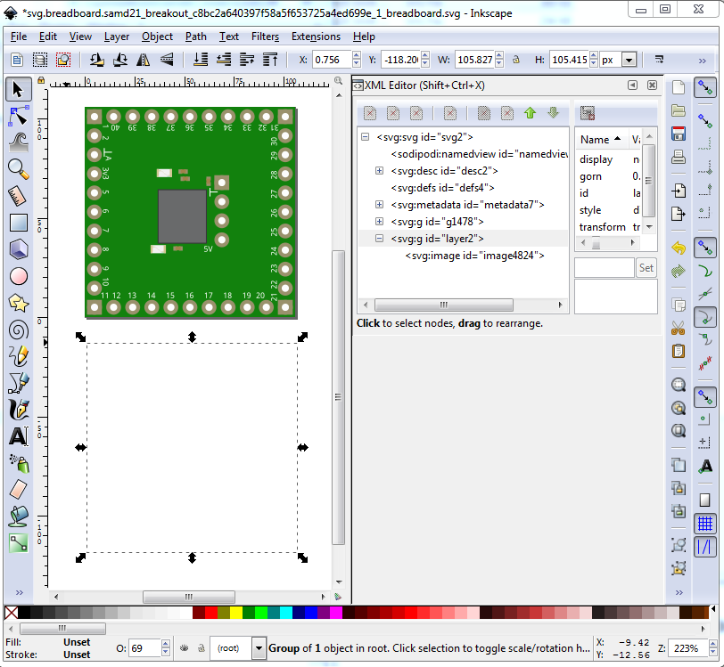
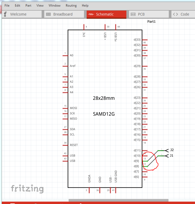
remove the image which doesn’t do anything (here I moved the image down about an inch to see what was in it.) This won’t hurt anything and so could be left in.
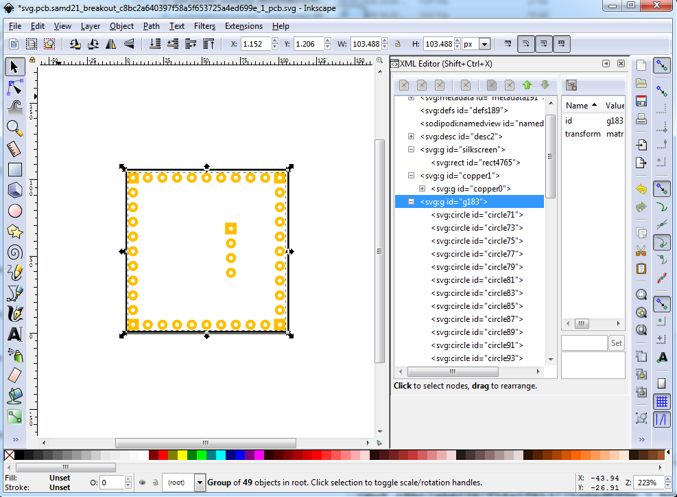
pcb
group 183 is unneeded (and likely what is causeing Parts editor to complain)
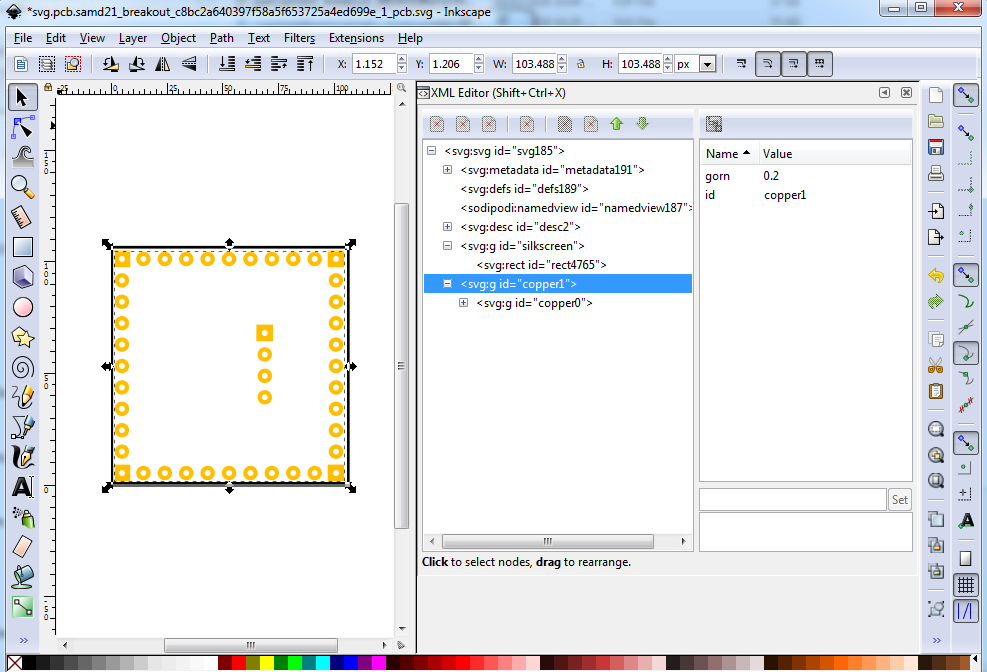
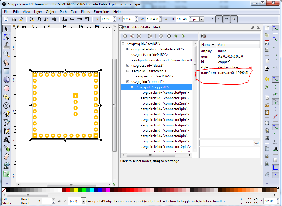
copper0 has a transform that isn’t in copper1 (which will likely cause problems in gerber output if the part is moved to the bottom of the board) so ungroup the whole thing to remove the transforms then regroup it.
The pad holes are likely too small. The calculation is hole diameter = pad dia - (2 * stroke-width)
currently that is 0.068 - 40 = 0.028in hole a standard IC hole is 0.035 so change the radius of all the pads from the current 23.779499 to 27.5 (giving a 0.075 pad diameter and a 0.035in hole) without moving the x/y coords of the pads.
schematic
removed several layers of redundant groups (from parts editor) otherwise unchanged.
fzp
    <breadboardView>
      <p svgId="connector0pin" layer="breadboard" terminalId="connector0terminal"/>
    </breadboardView>
should be
    <breadboardView>
      <p svgId="connector0pin" layer="breadboard"/>
    </breadboardView>
as there are no terminalIds defined in the breadboard svg. Didn’t change them because Fritzing will ignore them (and I am lazy  ) and us the center of the pin as the terminalID which is fine in this case.
Built a test file (incomplete in this case due to laziness again ) that makes sure the schematic terminalId is correctly at the end of the pin (I assumed the others were correct):
If your terminalIds are not correct the wire won’t terminate at the end of the pin. They are correct here and I assume also on all the rest of them. Then export the gerbers for the test sketch and edit the drill.txt file to check the hole sizes are correct:
from the drill.txt file:
; NON-PLATED HOLES START AT T1
; THROUGH (PLATED) HOLES START AT T100
M48
INCH
T100C0.038000
T101C0.035000
%
The 0.038 holes are for the headers and the 0.035 holes are for the IC holes as desired.
The corrected part (I was too lazy to change the moduleId and file names so you willl need to unload your current part to load this one or change the moduleId and file names of the svgs to be unique to load them together)
28x28mm SAMD21G-fixed.fzpz (28.1 KB)
and the test sketch
test-Sketch.fzz (30.9 KB)
Peter