This is odd and not something I have seen before! I assume you made this from the mystery part (I have not ever done much with the mystery part)? I’ll have to poke at it for a while and see if I can figure out what is wrong. Moving the part in schematic causes the connections to reestablish, but the outline is still offset.
edit:
Bad news: it is a bug, probably in the parts factory code.
Good news: I have a work around that doesn’t require the bug to be fixed (which will take some time):
workaround:
drag in generic IC set it to 2 pin sip blank the chip label
rotate part 90 counterclockwise
rotate label 90 clockwise
right cick on part and select Edit (new parts editor) to edit the part.
In the parts editor window select File->save as new part
(optional) in the metadata tab enter new description and parts values to match the new part.
click OK to accept prefix prefix0000 (its value is unimportant)
In your mine parts bin you now have a new part, if you right click on that and select export part you can write the part to a .fzpz file such as Zeitschalter.fzpz
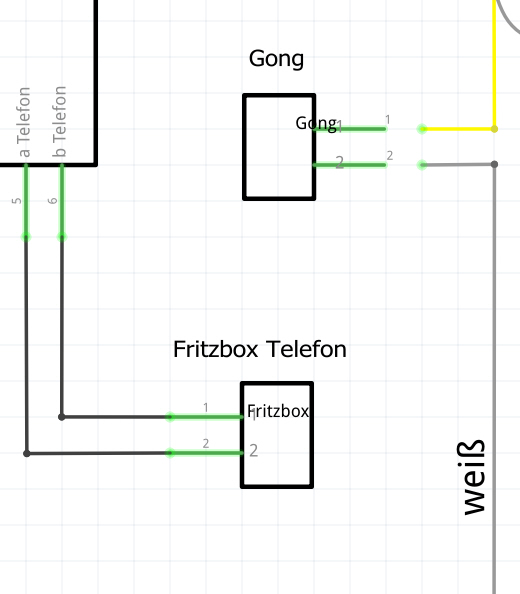
I did that then loaded your fzz file:
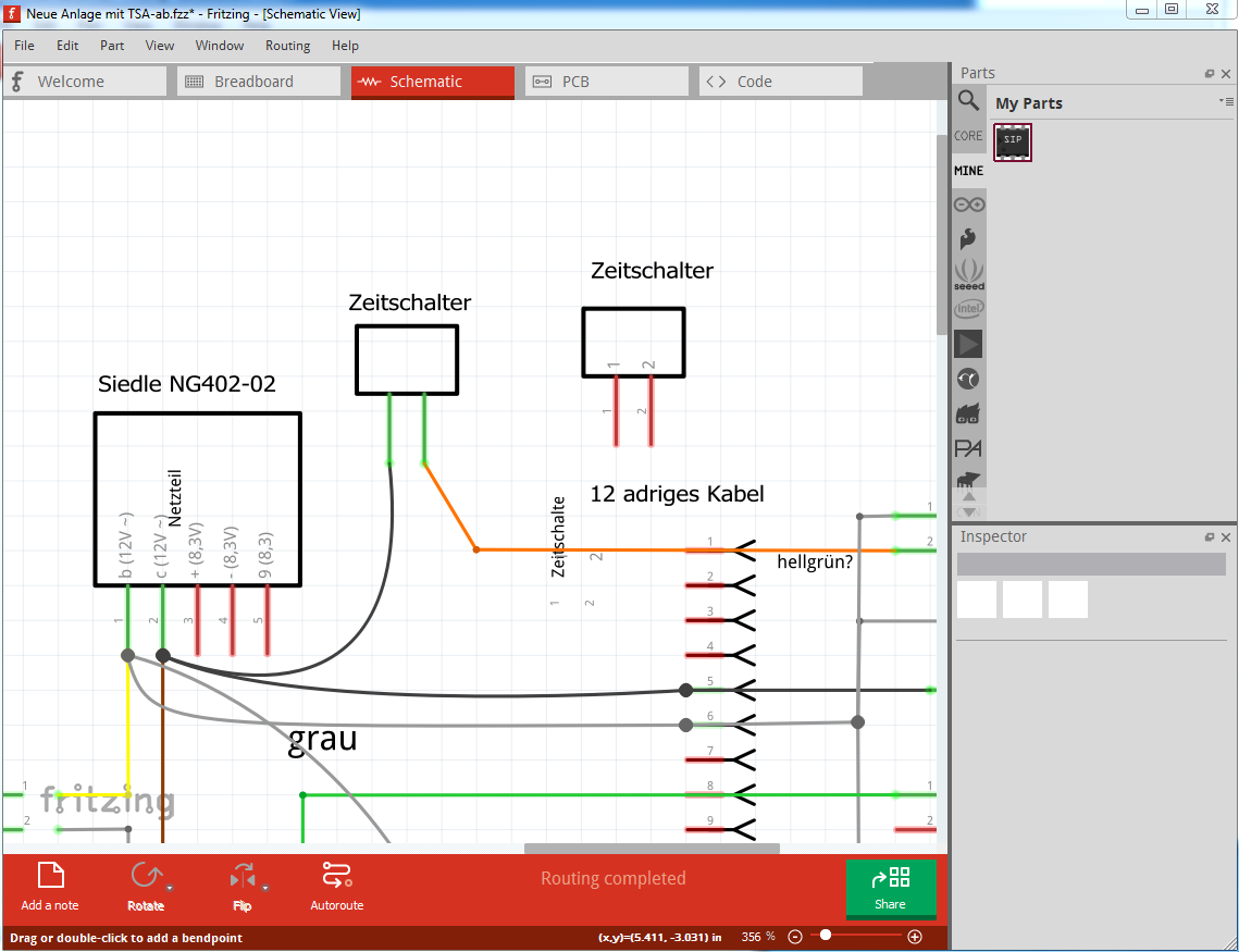
and loaded the new Zeitschalter.fzpz (which will be in the temp parts bin in the fzz file below) in to the sketch. Then I right clicked on your original part and did “delete minus”. That deletes the parts but leaves the wires in place:
circled in red in this image. Now I drag the new part to near the wires, then click on the end of the wire and drag it to the correct pin on the new part where it turns green to indicate connected.
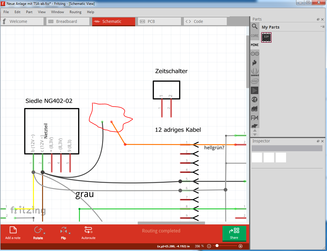
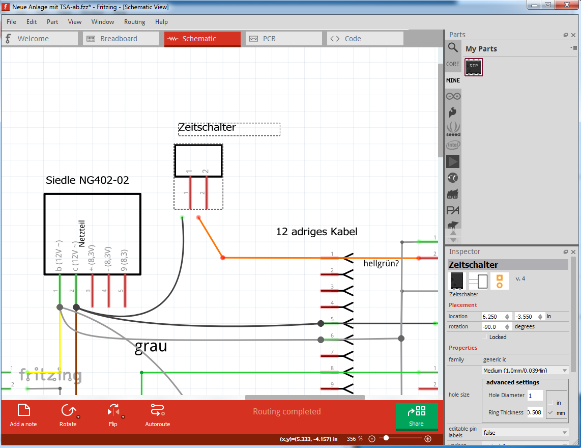
Do the same with the other one and you are done. This will now save and restore as a .fzz file because the new Zeitschalter.fzpz part is no longer connected to the parts factory, so it doesn’t get changed (and hit the bug) when loaded. You can do the same thing to any other parts that do this as well.
drag the ends of the wires to the parts pins
and the .fzz file the above came from:
Neue Anlage mit TSA-ab-1.fzz (20.2 KB)
Peter