I’m attempting to add power rails to my PCB design, however, I’m stuck with how I would approach this or if there’s a tool built in that would allow me to do this. Thank you.
What do you mean by power rail? I’d expect that to be an extra wide trace (which you can make by selecting the trace width in Inspector

bigger
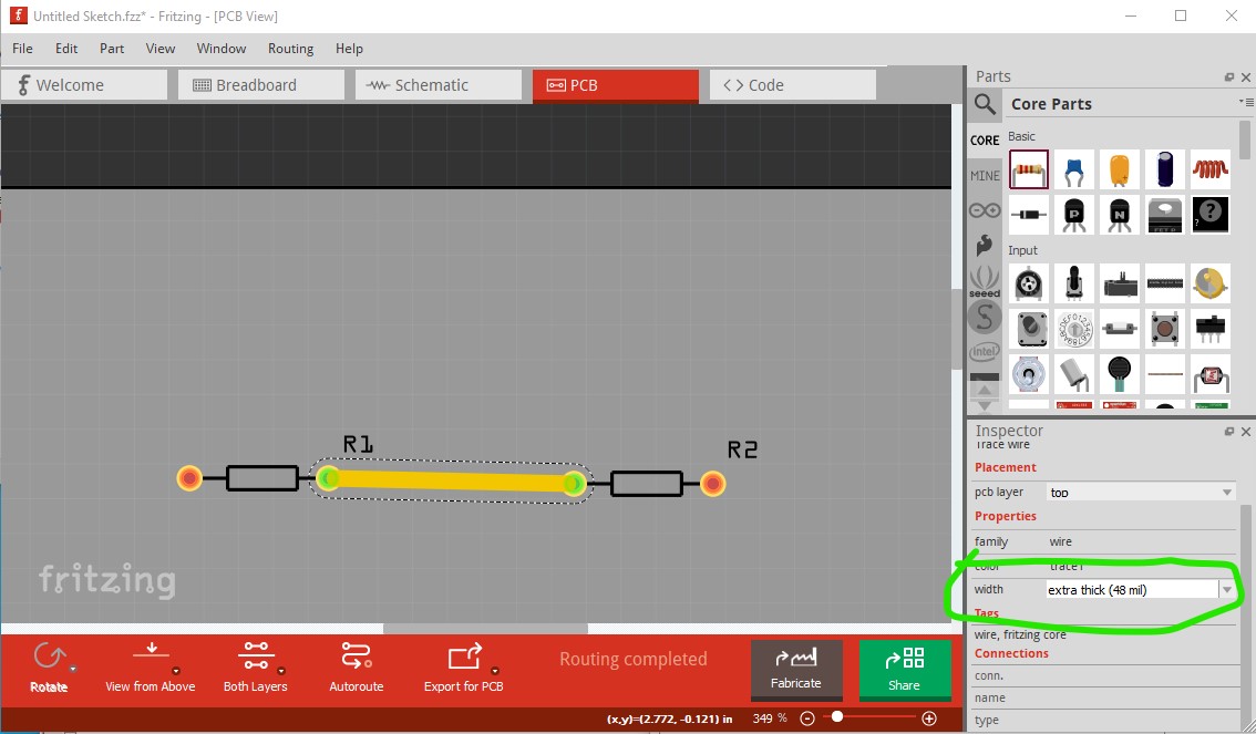
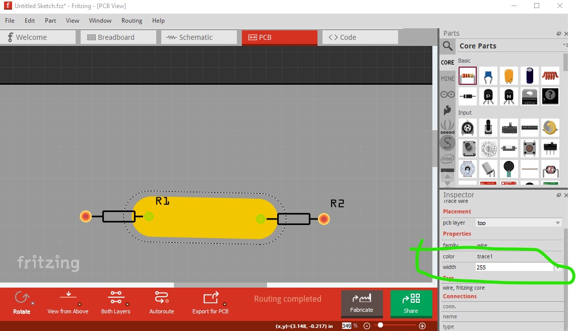
or you can type in a size up to 255mil (although you need to check the generated gerbers because there used to be a bug which didn’t center the pad correctly …)
beyond that you can do copper fill to use all the available copper in a given area.
Peter
Hello,
Sorry let me clarify, by the power rail I meant a design similar to these types of PCB prototype boards.
