I’ve probably done something stupidly wrong here, but after quite a lot of time of debugging and unable to understand exactly what the issue was, I thought I’d ask for some proper help.
I’m trying to design a PCB, which is powered by a generic two pin header. The issue is that in the PCB view the ratsnest takes negative to positive, or vice versa, then out to the rest of the board, which breaks routing.
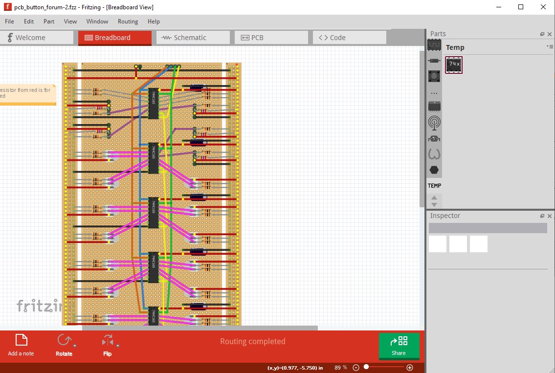
I’ve checked connections in breadboard view, everything looks to be okay as when I click the individual positive or negative pins, all of the correct connections light up.
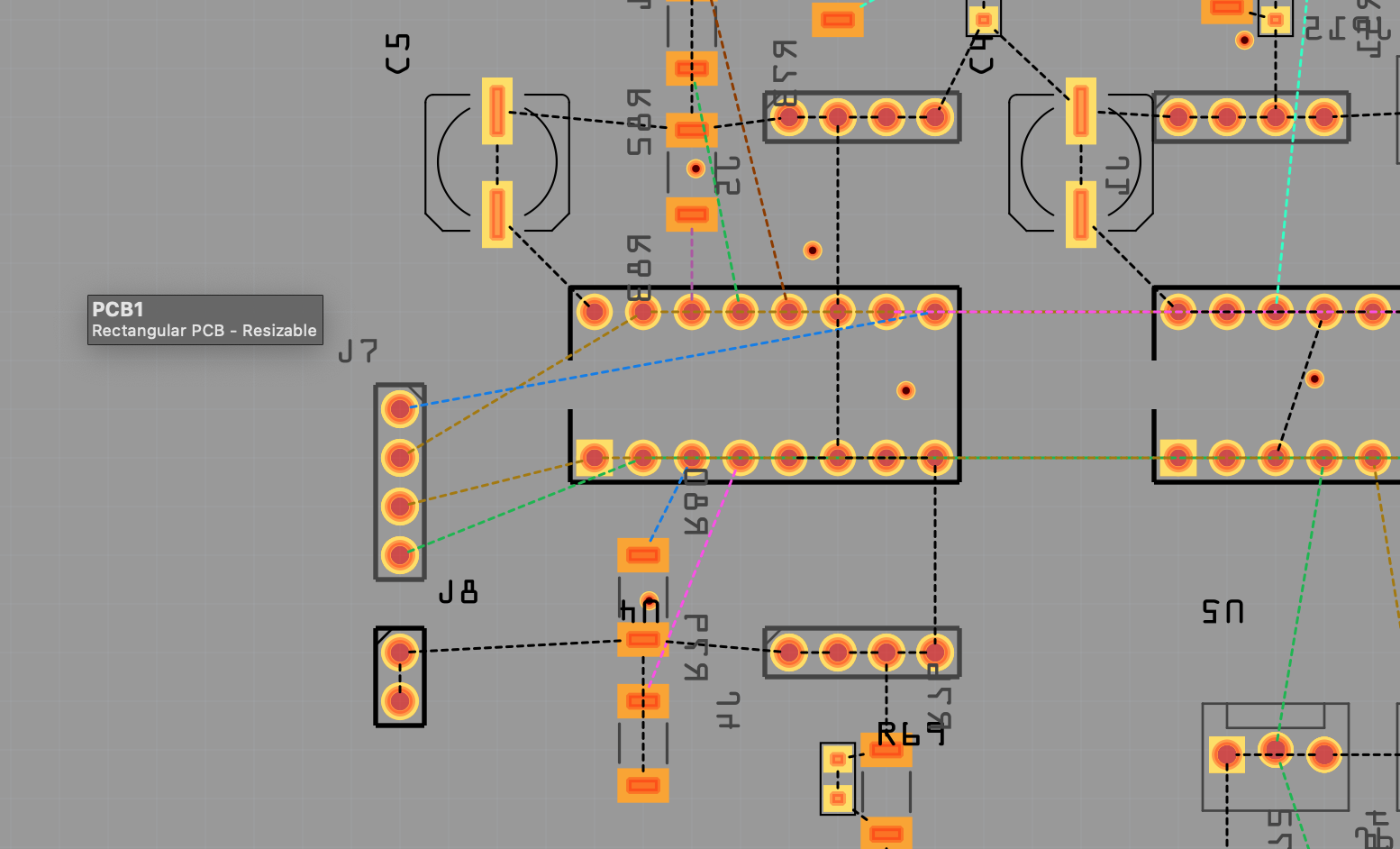
We can see this in the screenshot below for J8 - I expect two seperate ratsnests out from the header, but they merge into one across the pins.
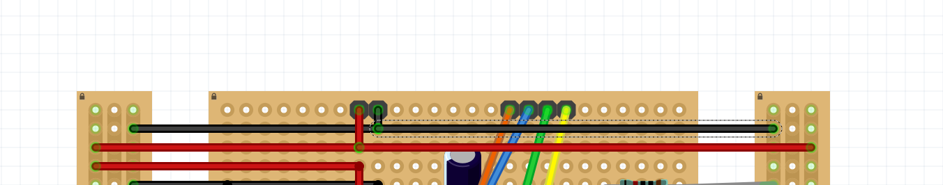
It looks like you have caused routing database corruption. Typically that happens because you made incorrect changes in another view that caused shorts and the shorts remain when the bad connection is removed. We have never been able to reproduce this problem to fix it, and the usual answer is to start the drawing again from scratch and complete one view completely (such as the current case with breadboard which looks correct.) Then do the other two views by clicking on the rats nest lines and routing them (as they show where Fritzing thinks the connection should go.) That avoids making wiring errors that may lead to database corruption. If you click on a pin all connections to that pin will light yellow. In breadboard all seems fine, there is no power to ground short:
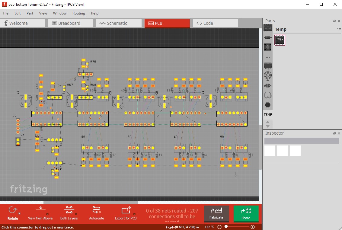
here only the power wires light yellow, ground does not indicating no short. In pcb the opposite is true (which indicates routing database corruption because the views should be the same!)
there are a lot of unexpected shorts. Doing Routing->select all wires in breadboard and then hitting delete does not cure the problem (but there are still wires connected because of the resistors.) Usually if you remove all the connections the routing database will reset leaving you with the components ready to wire, but that doesn’t happen in this case. Several other oddnesses (none of them necessarily wrong!) the leds appear to really be a pin header (presumably because we don’t appear to have a re/green LED part which surprises me!) which shouldn’t be an issue. In pcb the chips are shown as on top of the board as is usual:
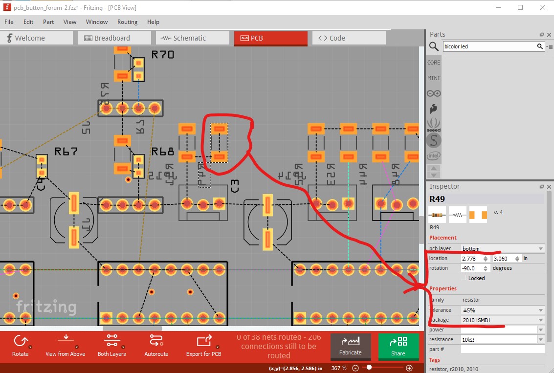
but the resistors are both SMD and on the bottom of the board (by default they are on the top!) Again this isn’t necessarily incorrect and not the cause of this problem, but it is unusual although there may be a reason for it.
I’m afraid your best bet is to start the sketch again from scratch, and wire breadboard to match the current layout and see if that corrects pcb (which it should!)
Thanks, we still have to fix it then.
Could you remember anything that could help us to reproduce it? Any action that you performed just before detecting the shortcitcuit?
Unfortunately Fritzing doesn’t see anything wrong. I have been seeing these (around 5 cases over the last 5 years) after they occur, but even when I repeat what I think the user did, I can’t get the fault to occur. If we can figure out how to reproduce it then we can probably fix it, but without that there isn’t much we can do since we don’t know what causes the problem. Yours is the first case we have seen on version 0.9.9 (the rest have been earlier versions) so it is useful to know that it hasn’t been fixed yet.
I don’t know about a specific action that caused the short circuit, but I know that working with large perf boards often caused performance issues which sometimes lead to crashing - often the files to recover were unusable. Furthermore, I worked with this particularly file across Linux, Windows and Mac devices, not sure if that would also be a contributing factor.
Finally, this was one of my first Fritzing projects and I did a lot of experimentation with design iterations, possibly it was something during this phase?
I know this isn’t much help but I will keep an eye out if I can reproduce again.
This is unfortunately fairly normal. There is usually a lot of things that have happened before the corruption is noticed. The last one I saw was more straightforward, in that there was (I think anyway!) a single mistake due to an odd part where power and ground got reversed in schematic while correct in breadboard. However even with that, I have not been able to create a sequence of changes that cause the corruption. There is some specific set of actions that causes the corruption (it looks like a delete did not complete for some reason leaving enough elements around to cause the corruption but I don’t know why), but it isn’t at all obvious what the sequence is. Until we can reliably reproduce the problem we can neither trace the issue to fix it, nor be sure any fix has actually fixed the problem. It may be that we need to add the facility to save the undo stack in Fritzing to a file so that once the corruption occurs it would be possible to step back through the undo stack to see how the issue occurred and hopefully reproduce it by reapplying the changes. I’m however not sure that is feasible, I expect it may be difficult to write the undo stack out to a file and that file may get very large, usually for no purpose because this happens very rarely.
Unfortunately I cannot upload all of the required media in one post, but now, if we only allow the two pin power to go to one side of the rails (in an L shape as opposed to an inverse T ship) this resolves the issue.
Let me know if you need more info or have further findings
Excellent news. Great that you found a way to reproduce the issue. However, I am a bit confused. Could you tell us how to reproduce it in our computers?
The best way would be some instructions on a minimal example such as STEP1: Add a protoboard of 9x10, Step2: Add a resistor, STEP3: etc.
If you can not find a minimal example , you are also welcome to upload the currect file and give us some steps as before.
Thanks for finding a way to reproduce it!
Where did you start from? If I use your original .fzz file above I can make this happen too, but I think it is a result of the database corruption (because pcb still shows nets to be routed, indicating the routing database has not been cleared.) I took your original .fzz file, and deleted all traces in all views (which still leaves ratsnest lines in schematic and pcb!) and then moved the components in breadboard until there were no connections in any of the 3 views. That should clear the routing database and now I am going to rewire your circuit and see what happens (I expect it will work correctly! but we will see.)
Hey to confirm this was a brand new fzz. regarding how to reproduce, can someone allow my ability to post more than one image per post and i can give a detailed set of instructions
That is excellent news! I can’t increase your post limit (I think it increases with either time or number of posts) although the admin may be able to. How about just describing what you did one step at a time in text and I will try and reproduce it (what Fritzing version you are using may be important too, I am currently on 0.9.9 but have older copies if you are using something older. I would suggest you post the .fzz file without the power wires then state in text which wires you added in which sequence to cause the fault. With that I can start from your sketch and see if it recreates for me (which will be awesome if it will!) as well as make sure the routing database corruption hasn’t already occurred in the base .fzz file. Alternately you can use multiple posts (which while a pain, should work!) with one image in each post.
@catwowe99 , If you can explain us how to reproduce the error, we can fix it!
You are welcome to send us a mail or write a link to a Google Docs or similar, if that is better for you. Additionally, you could also write an issue in github: