This sensor board offers all the needed components to implement the Pixart PMW3360DM-T2QU high end gaming sensor. High speed motion detection up to 250 IPS.
Not a bad job, but a few problems. First the svgs are dimensioned in px, inches or mm is a better bet as Fritzing will guess at which of the 3 dpis was in use and often (and perhaps in this case) gets it wrong. That said the dimensions on your part appear wrong, and there isn’t enough information available for me to correct it. The pin spacing appears to be 1.9m (it probably should be 2mm), and the board shows as 1621mm where the data sheet says it should be 2128mm. I left the dimensions as they are because I don’t have one of these boards to compare. In pcb I copied in the breadboard image and set the silkscreen to have the same (incorrect) dimensions, and added the two mounting holes in silkscreen (they won’t be drilled, if the user wants the holes they need to drag a hole in to the sketch and position it over the hole in silkscreen.)
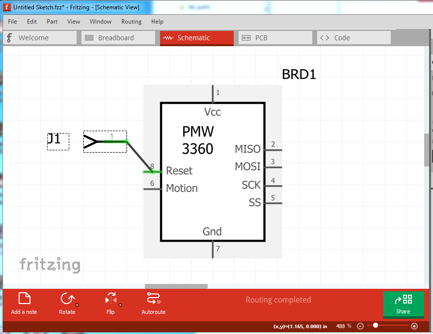
Schematic had a number of problems: missing terminalIds which causes this:
the wire is terminating in the middle of the pin because there is not a terminalId defined at the end of the pin. As well the pins are not on a .1 boundary (which may be because of dimensions being in px). In the fzp file I removed the terminalId definitions from the breadboard layer (they are not defined and not needed in this case) and changed the type from female to male (which is the usual.) All of that is done in this part except as noted the pin pitch and board sizes appear incorrect.