I created a circuit on the breadboard connecting a XAIO with a TCA9548A and a couple of 128 X 32 SSD1306 OLED displays. The idea is to program the microprocessor to display two sets of data at the same time.
It is my understanding that the schematic and PCB board tabs should follow the breadboard tab, and vice versa. Such is not the case, however.
Can someone check out my file and tell me where I am dropping the ball?
PS - the power wires for the XAIO were relocated but consider appropriate jumpers in place. I am mostly concerned with why the schematic is dropping all of the breadboard information.
This one took me a while , the problem is you duplicated the breadboards and there are two one under the other. Some wires connect to one breadboard and some to the other. Delete one breadboard and things should work normally.
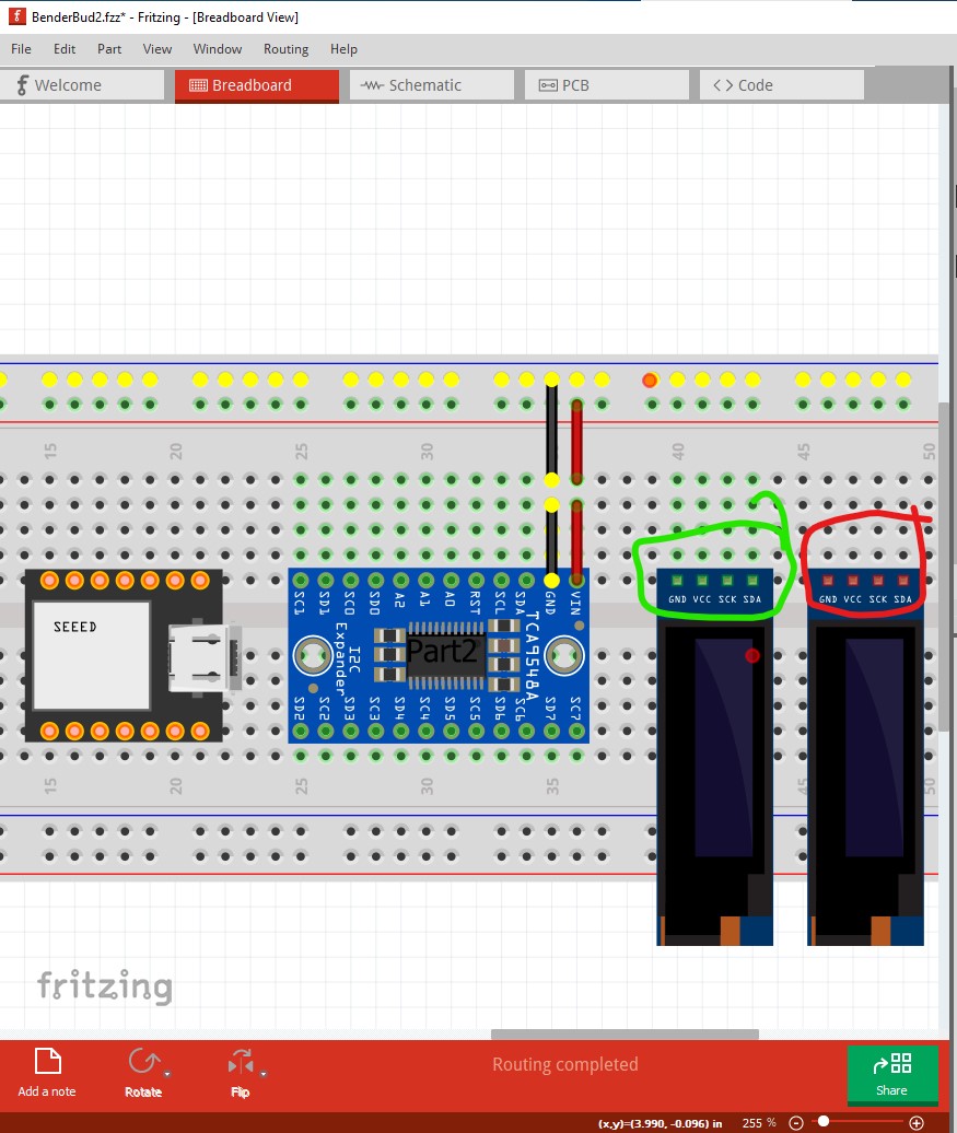
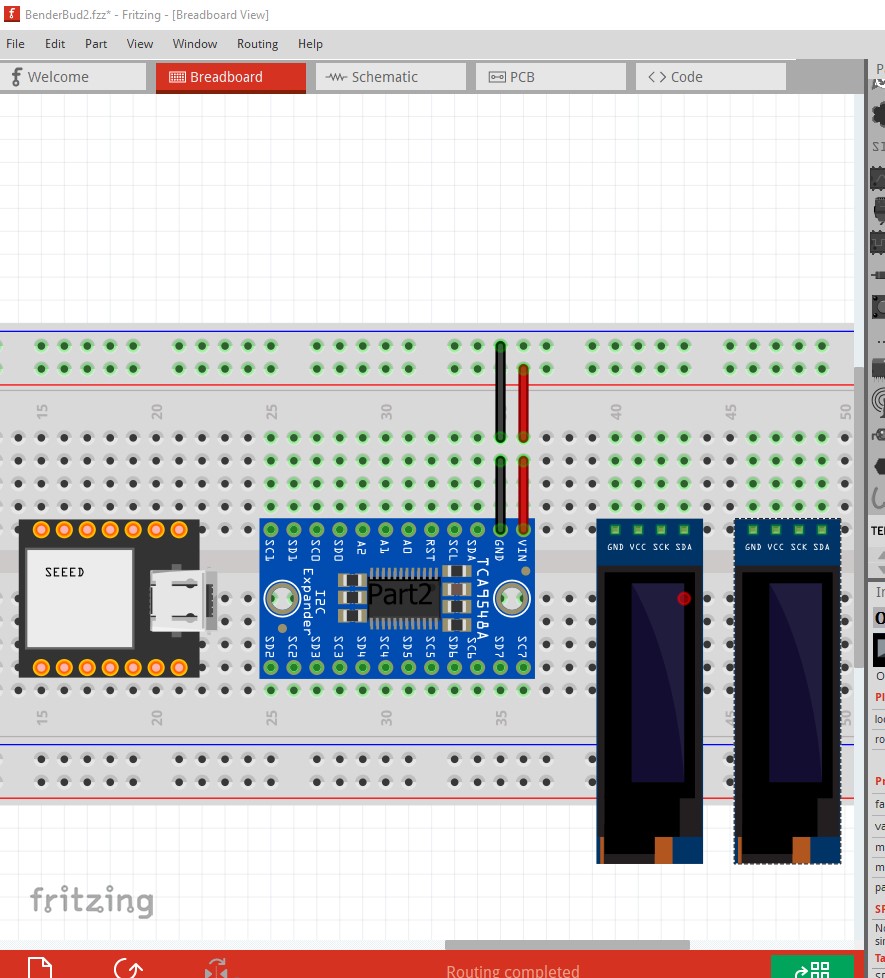
Note the left OLED has green pins and the right does not (indicating it is not connected to the breadboard.) To fix that move the left OLED up and down one pin, the movement will trigger the connection like this:
Thank you for that information and breakdown of the Fritzing system. I appreciate your time and effort that you committed to my issue. I simply started over from scratch and everything worked fine.
Fritzing has the unfortunate habit of duplicating parts on top of each other so if you accidentally hit duplicate while the breadboard was selected you will have gotten two breadboards on top of each other. As I said it took me a while to figure out what was wrong as it wasn’t at all obvious. Some of your parts were connected to one breadboard and the others to the other breadboard, and the two breadboards don’t connect to each other. Thus the lack of wires in schematic.