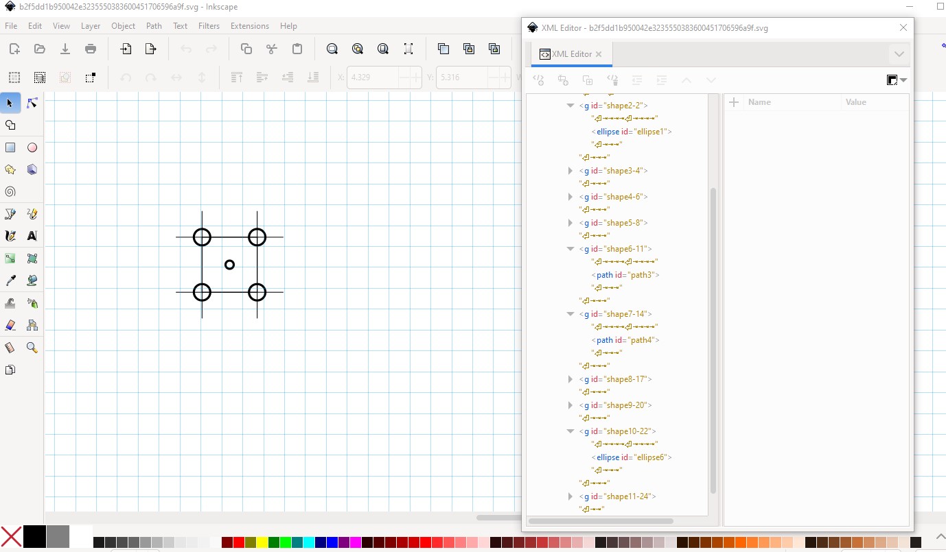
It is probably possible, I’m not sure it would be useful. Your svg has no groups (it needs copper1 and copper0) to become a part) and no connectors. To be a part it would need a breadboard and schematic svg along with a .fzp file.
Peter: I intend to use this as a template part. I would drag it onto the PCB and lock it into position. Then I would drag holes onto the PCB drawing and line the holes up with the template holes.
Once all 5 holes are placed onto the PCB drawing and overlaid atop of the template holes, I would lock them in place, specifying the hole diameter and copper ring thickness.
Then I would remove the template drawing and connect four of the holes to the ground plane and the center hole to the circuitry on the PCB.
Then the suggested method (loading the image in to silkscreen) should work fine. As long as the template is the correct physical size. You can then drag holes in to position and then delete the image.
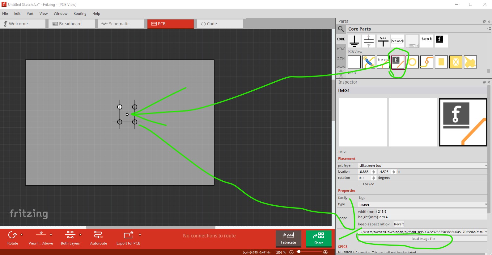
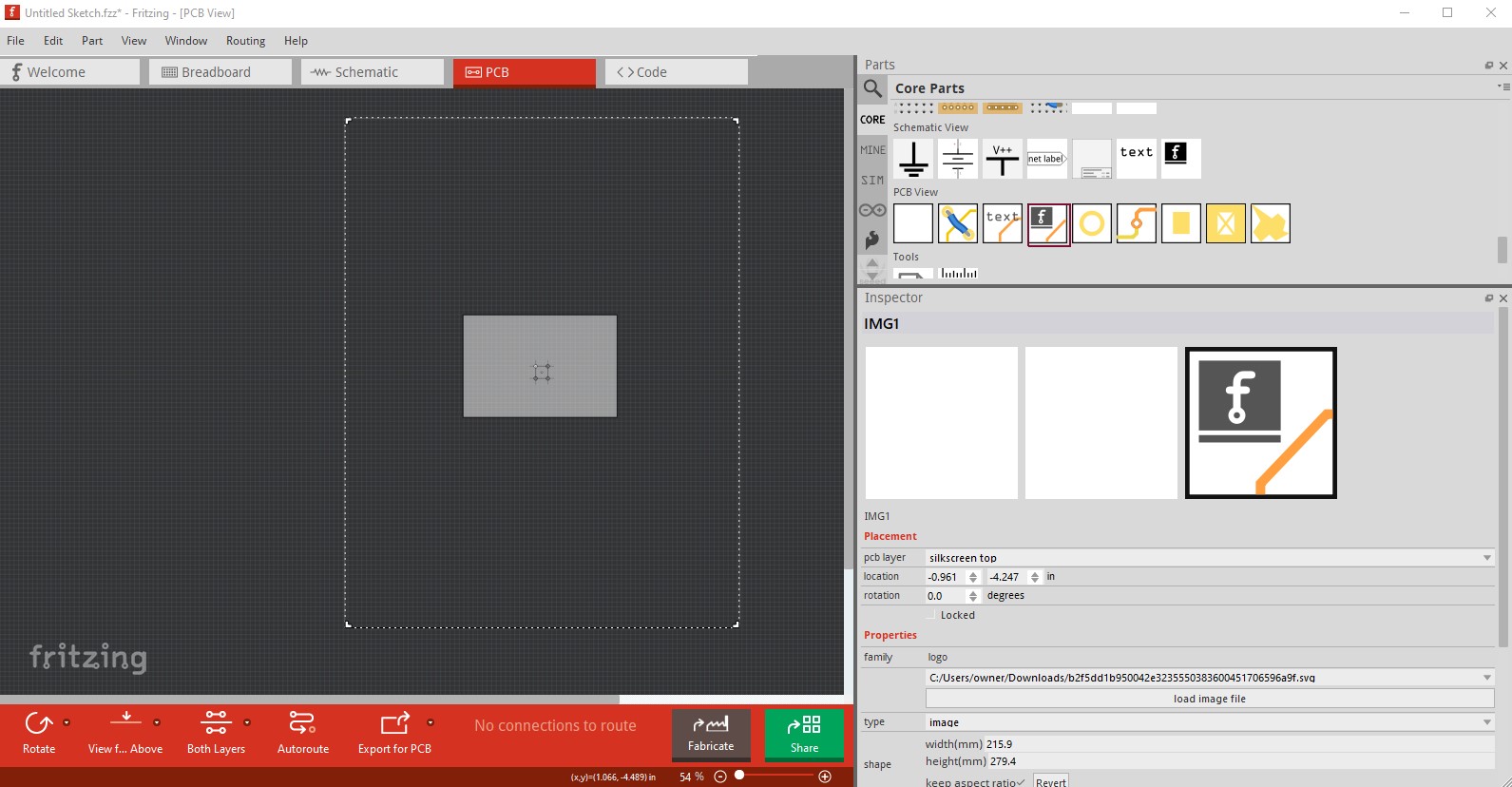
By following the image above. Drag the image icon from the parts bin in to the sketch then select it in the sketch, then in Inspector (the lower right window) select load image file and select your svg and it will load in to silkscreen as illustrated. The image can be moved like any other part.
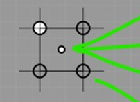
Once you drag the image icon in to the sketch you then need to click the load image file tab and select you svg file. That will load the image in to the sketch like this
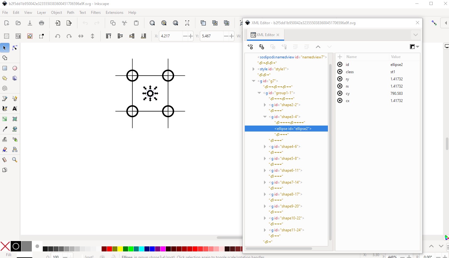
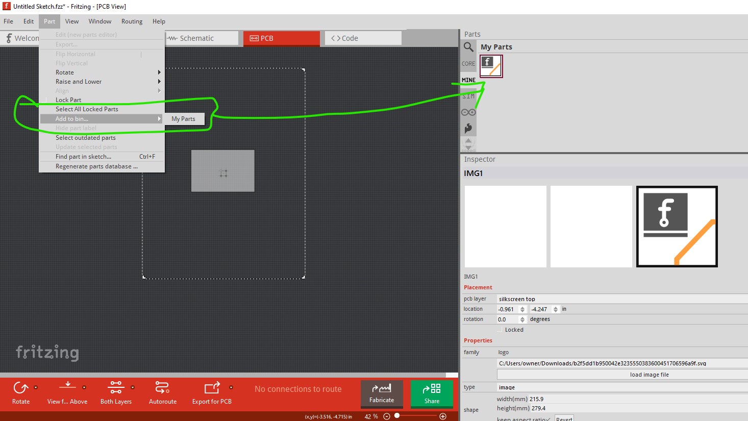
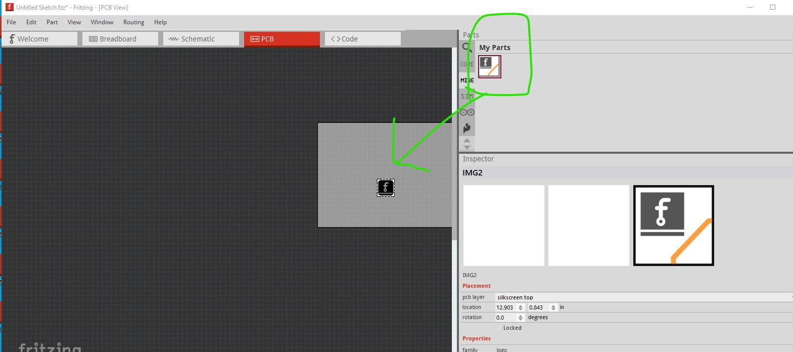
The bounding box is so large because you svg is that large, you would need to reduce its size in your svg editor to get it smaller. Then select the image in the sketch, and it will store the image in your mine parts bin. From there you can drag the image in to a sketch later without having to do the load image file.