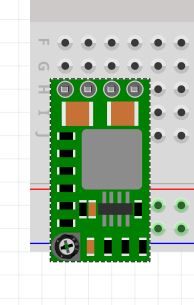
Hi - I’m new to Fritzing but trying to learn to make my own parts. I’ve successfully created the part (a DC-DC buck converter) and it connects to pins/breadboard sockets if I use wires in the breadboard view. However it won’t directly connect to the breadboard the way typical components do. It looks like everything lines up and I know I used a .1 in pitch in the svgs, but for some reason it just won’t connect…I’m not getting the green lightup indicators on the breadboard. Could someone take a look and let me know what I’m doing wrong?
The breadboard connector pins are marked as “female”, only “male” pins will connect directly to those. The connectors in your part are marked as “female”.
In addition:
You have a “copper0” layer specified in the part definition (fzp) file, but no matching id exists in the pcb file. The easiest fix is probably to change (in the pcb svg file) the “copper1” layer to copper0, then change “layer2” to “copper1”.
The pcb svg file has a rect element with an id of “silkscreen”. “silkscreen” should be on a group (g) element instead. Remove the existing id, then change “layer3” to “silkscreen”.
The breadboard svg file does not contain an id to match the “breadboard” layer specified in the definition file. Change “layer1” to “breadboard”.
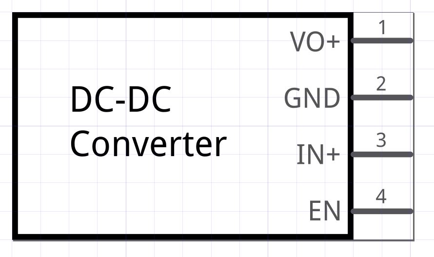
The schematic svg file does not contain an id to match the “schematic” layer specified in the definition file. Change “layer1” to “schematic”.
Without the schematic and breadboard layer ids, the part will work in the Fritzing application, but the part will be dropped when exporting to an svg image.
That is a lot less errors than a typical “first part”.
Thanks for the help! I think I have everything fixed, and the pins automatically connect to the breadboard. The last issue I’m dealing with is the fonts in the schematic view. I have attempted to make them Droid Sans in Inkscape, which I can verify is true in the xml editor, but when I import the svg into the Fritzing parts editor, it says "Fritzing currently only supports OCRA and Droid fonts - these have been substituted in for the fonts in ‘C:/Users…DROK_voltage_reducer_schematic.svg’.
Nothing ‘doing’ wrong. It is from a difference in the way that Inkscape and Fritzing store font information in an svg file. Since you are using XML editor, you should see that the properties show “font-family:Droid Sans;” and right with it, "-inkscape-font-specification:‘Droid Sans, Normal’;. The first one is normal svg, the second is an Inkscape specific extension that Fritzing does not handle. You could use the xml editor to delete the inkscape piece, but it will get added back the next time you touch the text or group in Inkscape.
One “fix” for the problem, is to save the file using “save as” and selecting “optimized SVG”. In the “Optimized SVG Output” control that opens, on the “Options” tab, select “Convert CSS attributes to XML attributes”. That will replace the “style” attribute with multiple individual attributes, getting rid of the inkscape special tag in the process. I also check:
Collapse groups
Create group for similar attributes
Work around renderer bugs
On the SVG Output tab:
Remove metadata
Remove comments
Format output with line-breaks and indentation
Strip the “xml:space” attribute from the root SVG element
On the IDs tab:
Remove unused IDs
Preserve the following IDs: “breadboard,copper0,copper1,silkscreen,schematic”
Preserve IDs starting with “connect”
Older versions of Inkscape, or actually the optimized output module, have been reported to cause incompatibility problems with Fritzing. I do not know if it was the code, or user settings, but with this version (Scour 0.31+), with those settings, for what I have been doing, it works, and cleans up the SVG produced by Inkscape quite well. Those optimization settings are remembered across sessions, so they only need to be setup once.
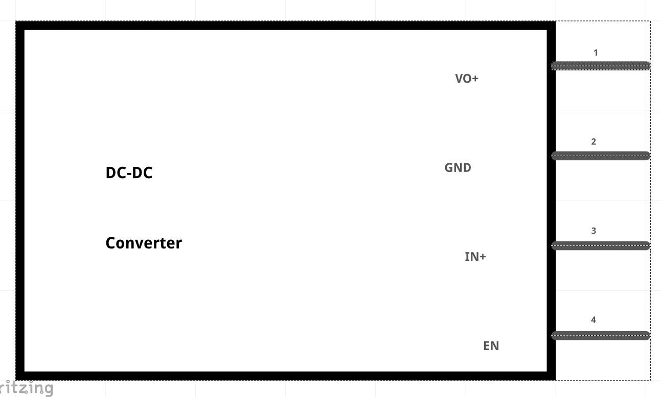
Great, thanks again. I’m not getting the error now, but it’s still pulling in an image that looks drastically different (and unreadable on the schematic) into the parts editor. Here is the comparison:
That is likely another Inkscape / svg / Fritzing implementation difference. Fritzing does not like “px” (or anything else) as unit for font-size attributes. This one is really Fritzing’s fault. The unit value is valid SVG. If you look at the svg file (with a standard text editor) after saving it from Inkscape, you will probably find something like ‘font-size=“2.5px”’ for the text elements (or the group they are in). Change that to ‘font-size=“2.5”’. Before importing into Parts Editor.
All of these little ‘tricks’, that you just have to know. The FritzingCheckPart tool can be used to do some cleanup, as well as reporting certain kinds of potential problems. I do not like/agree with everything is does and reports, but fixing the px issue is one of the things it does right. It will also fix the font problem that I did using the save as optimized svg.
I don’t think the “px” is a FZ fault. The number in question in INK is a multiplier, so shouldn’t have units. I submitted a bug on the INK Git and the guy that answered said it shouldn’t really have units, but it looks like no one is interested in removing it so we have to fix it on this end.
I am basing this on MDN information about SVG itself. Font-size shows examples with units of “em”, and points to CSS for additional details. Which shows more cases with numbers with units appended. In the raw SVG world, the units have meaning. Direct physical units (in or mm) should tie back to the main drawing units. Others, like em, need to be interpreted relative to some other base text size. Which Fritzing (and as far as I can tell, Inkscape) never sets up. px would be the size based on the viewbox, the unit (1) multiplier from that. It is not (or does not need to be) a simple multiplier. That is just the way that it is being used.
That’s the problem with XML code, there is 50 different ways you can do the same thing.
INK puts out this when you write text.
> font-style:normal;font-variant:normal;font-weight:bold;font-stretch:normal;font-size:1.5875px;line-height:3.30729px;font-family:'Droid Sans';-inkscape-font-specification:'Droid Sans Bold';font-variant-ligatures:none;letter-spacing:0px;word-spacing:0px;writing-mode:lr-tb;fill:#ffffff;fill-opacity:1;stroke:none;stroke-width:0.264583px;stroke-linecap:butt;stroke-linejoin:miter;stroke-opacity:1
1.5875 is not the actual height of the text in px, it’s a multiplier of the scale set at the start. You’re an expert and can code directly, but beginners have to use a drawing package, and they don’t care about CSS stds, they just want a drawing that works.
The whole problem is that FZ was written for Illustrator - it probably used the actual px size -, and it needs to be converted to handle INK without those little semantics. These little semantics is what kills it for beginners trying to use FZ, hence why they leave soon after. I can go into KiCAD and Eagle and not have to worry about “px”, quotes on fonts names, transforms, etc, but with FZ you need to expert to use what is essentially an easy to use beginner program. I’ve tried a few times to get INK change over the last 5 years, and no one is interested - they cite a different interpenetration if the CSS std, and that they are correct -, so FZ has to change if INK is to be used. Basically having to explain “px” day on day, is a waste of time for everybody.
While I’m not the original author, here is a corrected part. The schematic font sizes were all too small and misplaced and the holes in pcb were likely too small. The pcb holes have been increased to 0.038in suitable for a .1in header pin. Check the pcb footprint against a real part as I don’t have one.
Peter,
Thanks for the clean version. This was easier to navigate. I’ve updated your version to add a bit of text to the silkscreen and to the schematic to make it more obvious what it is and for the final board to have good silkscreen labels. The size of the device and the pinout do look correct to me. I do have these mini converters myself.
Can you take a look at my version and see that it looks clean to you. And if not, can you critique it so I know what I missed? I used Inkscape for the text additions and kept things in the xml areas as I’d expect to. Once I was done with the svg changes, I ran FritzingCheckPart.py on the fzp and it did make a few mods as I’m accustomed to it doing. Then I zipped up the files into this .fzpz and imported it. It looks good to me although I’m surprised at the boldness of the font in the PCB view. May be just because the font size was larger than the schematic text. Not sure.
As a general rule pcb in a part shouldn’t have text. The reason is that the user has to change the part to remove the text if they don’t want it, but if they want it they can add text to the sketch (without changing the part) if they want it there. That said it doesn’t hurt anything to have text in a part either.