Pins dont align and connect

Hello,

i have placed the DRV8825 on the breadboard but the pins dont seem to connect as well as align (no green trace and thus no autoroute)

drv

the installation is new and only about 30 minutes ago.

There is a slightly better one (pins work in breadboard) here (found via a google search for “Fritzing part drv8825”):

schematic looks to be wrong (it is the A4988 that this was apparently cloned from) and I don’t know about pcb so it would be wise to verify the footprint before ordering boards. I can clean the part up completely if you like.

Peter

oddly this version of the driver also doesnt work (align pins and connect them on the breadboard)

i have 5 of these drivers at home and can confirm that they will fit onto a breadboard.

would be nice if you could do that :slight_smile:

Looking at the original breadboard image, the …4N35 chip appears to be shifted slightly to the right from the breadboard connection points. It is obviously close enough to connection, but that makes me think that maybe the breadboard is not quite aligned with the 0.1 inch grid that Fritzing is using to position (snap) other parts. Try going to the View menu, make sure that Align to Grid is selected (has a check mark), then click Set Grid Size and verify (or set) the gird size to 0.1in. With that out of the way, click and drag the breadboard a little, to force it to snap to the grid. Then drag the parts at little to also force them to snap to the grid.

I have seen the breadboard get off grid like that when the breadboard size is changed in Inspector. That appears to be the normal “full+” breadboard, which starts out aligned, but if it was changed to something else, then dragged, then change back to full+, it could have ended up off the snap grid.

For parts that do not seem to want to align and connect to the breadboard (after snapping the breadboard to the grid), try going back to the view menu and change the grid size to 0.05in. Then drag the part again. Visually the DRV8825 part pins appear to be close to half way between the breadboard connection pins.

drv

i tried that before, didnt work but now at least this seems to work. But still they wont connect to the breadboard :confused:

From the symptoms visible, you are still trying to use the DRV8825 breakout board from the parts library. I just had a look at that, and my quick analysis says that (at least) the breadboard view image is broken. It does not have a breadboard layer in the svg image, and has connector ids on oddly shaped SVG path components. Just for more fun, it is using an internally stored jpeg image for the background graphics.

The alternative that @vanepp pointed to worked for me. It snapped to grid, and connected to the breadboard properly. Here is an image, and my sample sketch file that you could use to continue from.


drv8825-sample.fzz (201.2 KB)

The ‘normal’ way, would be to go to the post that @vanepp linked, open the part file referenced there, save that in your “My Parts” bin, then use that part in place of the one from the core library. That is effectively what I did to create the above. Watch the prompts when exiting from Fritzing. You should get messages asking to save the part and include it in the bin.

i opened your file, then saved it into “my parts” and now it works :slight_smile: only thing is, in the circuitry shematics it is named a4988 and scaled really big. Thank you

I have a fixed version (there are a lot of things wrong with the one in core.)

The new part:

DRV8825-fixed.fzpz (114.0 KB)

and a test sketch with both the original from core and the new part (new part on the left old on the right):

test-Sketch.fzz (129.3 KB)

The problem with breadboard connections is the connectors in the fzp file are set to pad. This is a legal (I think anyway) value, but I don’t know what it does (other than not connect to breadboard pins :slight_smile: .) The normal value is male (and breadboard pins are female. The rule is male connects to female but female-female do not (nor apparently do female-pad.)

edit: The usual use of female in a part fzp file is for a connector like the Arduino ICSP connectors that are typically at right angles to the breadboard pins and would thus short out if connected to the breadboard. Set them female and they will not connect (and thus short) but can still be connected to via a wire to the pin.

Wires connect to anything, so as you discovered you can use wires to connect to the original part on breadboard:

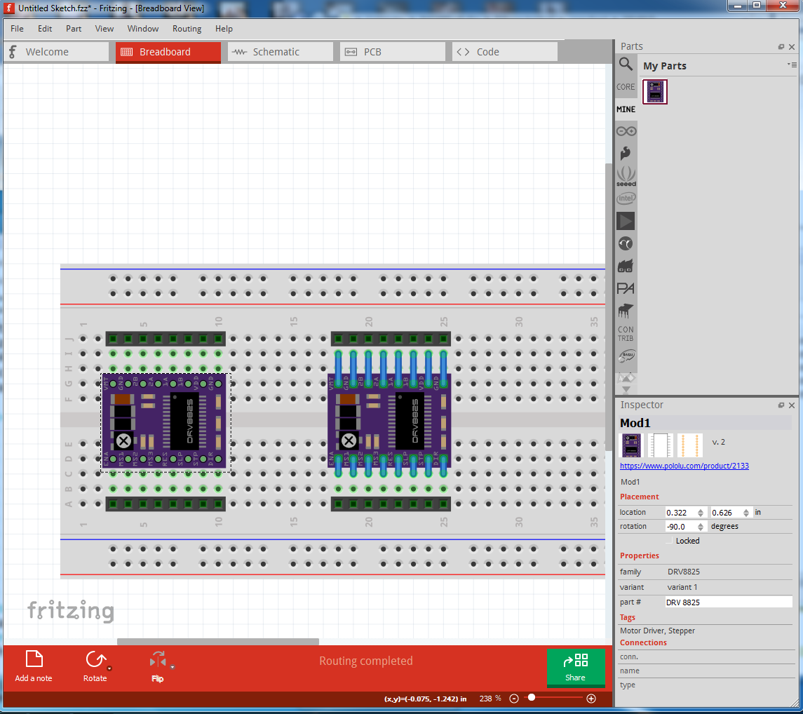
like this. The breadboard svg was also dimensioned in px which can (and did for Inkscape) cause scaling problems, it looks like it worked correctly in Fritzing this time, but that doesn’t always happen.

Schematic I just replaced completely with a new version (new part on the top in this one):

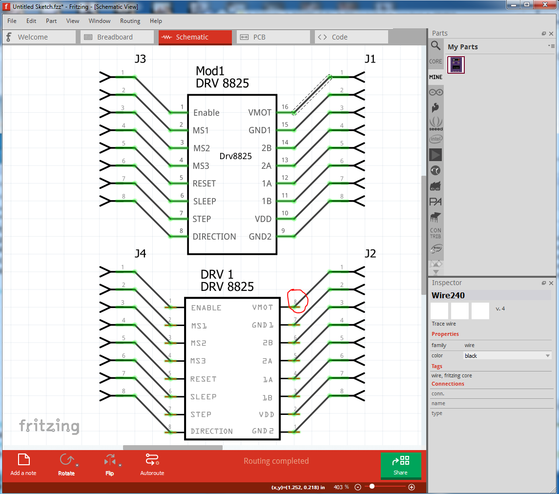
note on the original part on the bottom that the terminalIds are set incorrectly and the wire does not terminate on the end of the pin as it should (see the red circled VMOT pin for an example)
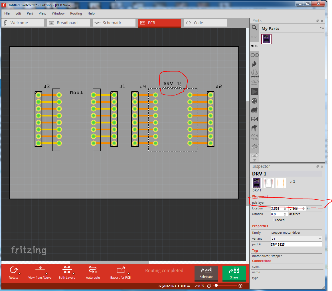
pcb:

pcb is missing the silkscreen outline (it is in the svg but likely has a translate that caused it to be truncated.) More importantly, the original part can not be moved to the bottom of the board (this is the new part, note that in the Inspector window on the bottom right you have a choice of top or bottom for pcb layer.)

on the original part that is missing (due to an error in the layer property in the fzp file) so it can only be on the top of the board:

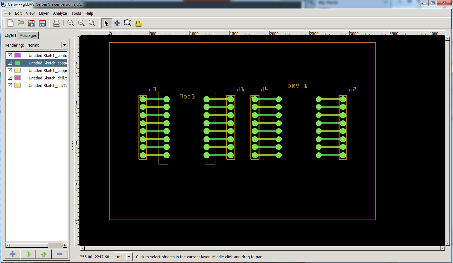
the layer selection is greyed out for the original part so you can’t move it to the bottom of the board. In the gerber output all the holes for both parts are drilled (this is only the drill and silkscreen layers in gerbv):

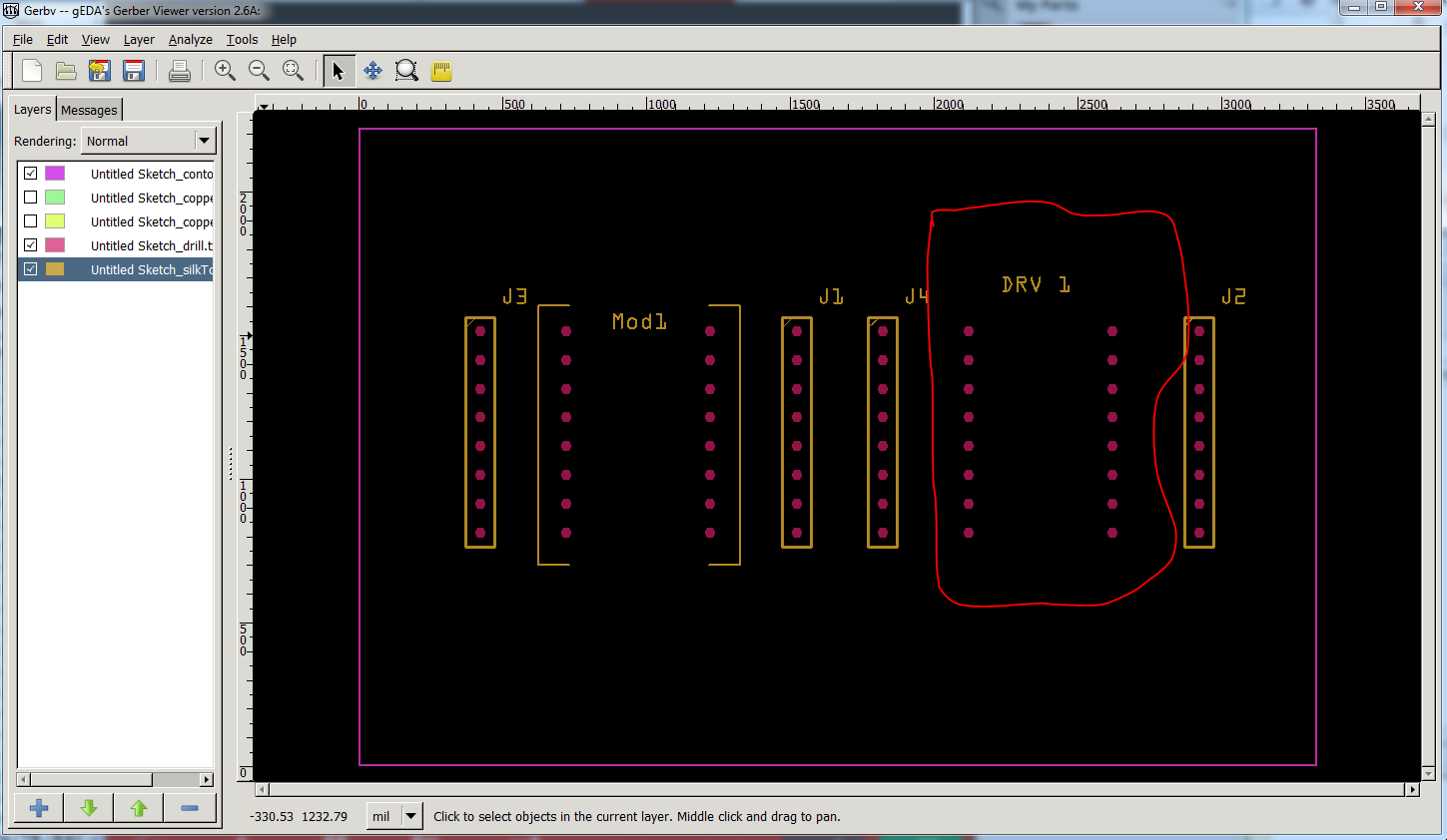
note the lack of silkscreen outline in the original part (circled in red.)

The same image with the top and bottom copper layers added back in:

finally, in the new part all the holes are 0.038in (the correct size for a .1 header) in the drill.txt file:

; NON-PLATED HOLES START AT T1
; THROUGH (PLATED) HOLES START AT T100
M48
INCH
T100C0.038000
%
T100
X017222Y015222
X017222Y009222
… for the rest of the pins.

In the original part we have three different hole sizes none of them the correct 0.038 (the ones present are for the new part and the headers):

; NON-PLATED HOLES START AT T1
; THROUGH (PLATED) HOLES START AT T100
M48
INCH
T100C0.037750
T101C0.037722
T102C0.038000
T103C0.037694
%
T100
X021222Y013139
X021222Y012139

at 0.037 something that probably won’t matter because the board house would likely round up to 0.038in anyway, but it is sloppy. All that said if you load the DRV8825-fixed.fzpz file above in to your mine parts bin (via File->open in Fritzing) then right click on the DRV8825 part in your sketch and select “delete minus” you will get this:

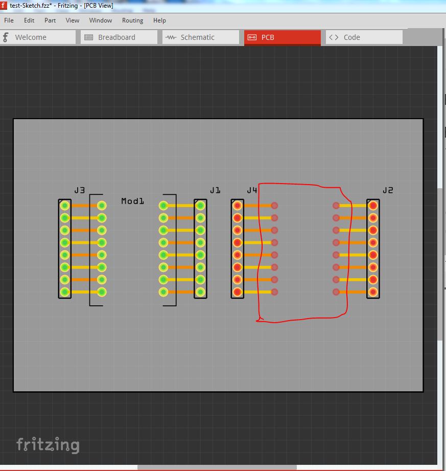
here (and in the other two views, the original part is gone but the traces remain. If I now copy in a new copy of the new part and click on the end of each trace and move it slightly, it will connect to the new part without having to reroute the entire sketch like this:

Capture7

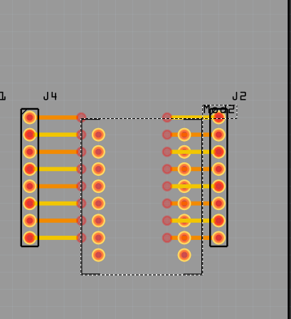
here the new part has been dragged in but not connected. now move it a bit and drag the end of the pin 1 trace til it connects (the connector turns from red to green):

Capture8

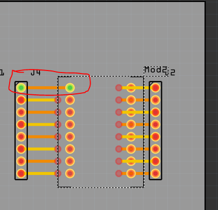
Now repeat this for all the pins in all three views and you have replaced the part without having to redo the routing (which may be quite complex!)

Peter

1 Like

Thank you very much! i think everything is working properly now. :slight_smile:

You are most welcome. As usual this was win-win, I have found a new error (the layer property being incorrect breaking being able to select the top or bottom of the board) that needs to be added to the part check script. As well eventually I’m hoping to go through core parts and clean them all up, and this one will be done (when I figure out how to obsolete the current part.)

Peter

Hi Peter - Just found this - sorry for the inconvenience, as when I did this it was a quick exercise in copy / paste for getting the part I wanted. Will have to upload your corrections on github … :smile:

Add : I also had the same problem, couldn’t delete the old version … :confused: