Hallo Zusammen,
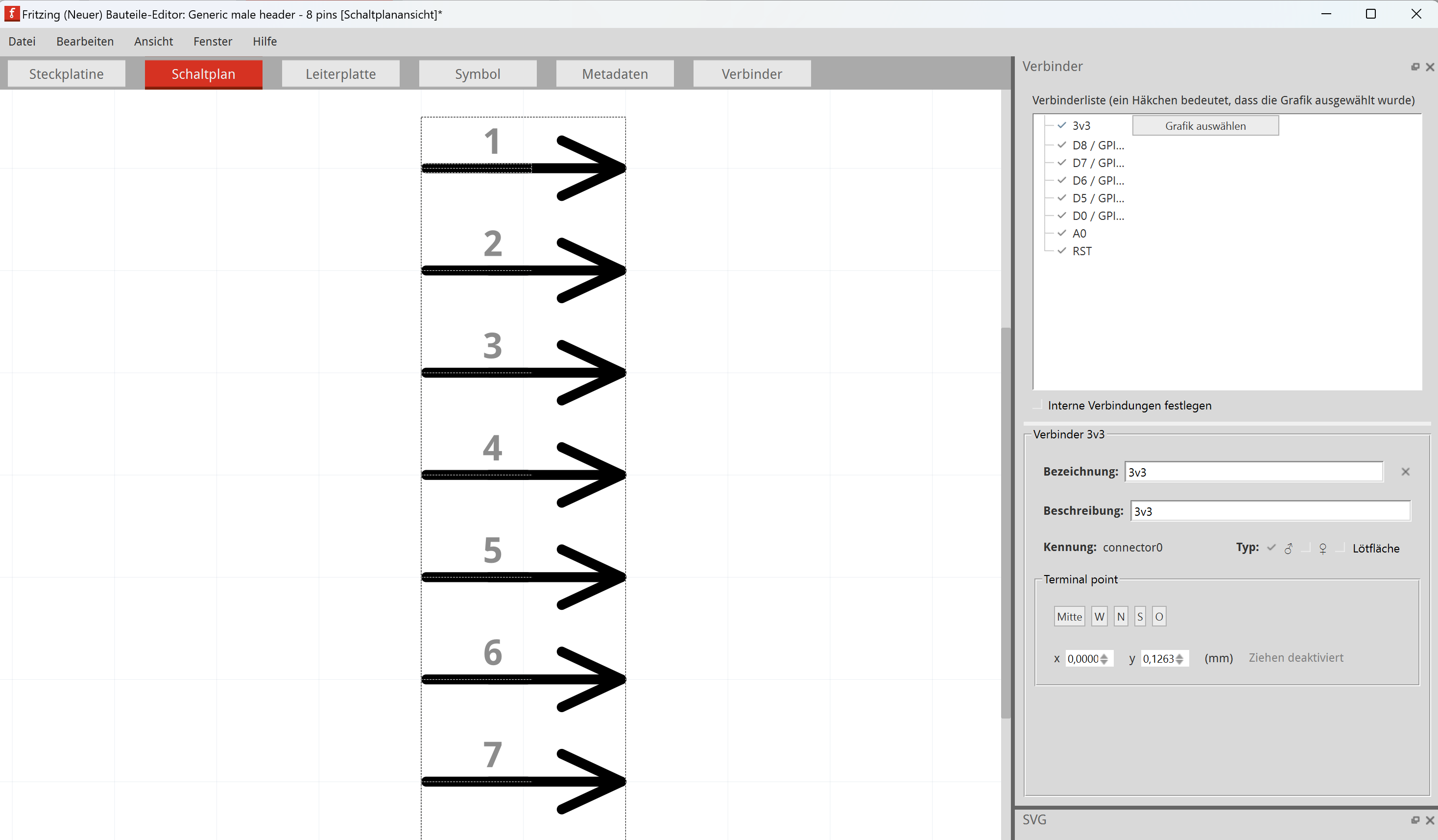
Ich habe mir jetzt ein Bauteil modifiziert und mal die Pin-Belegungen angepasst.
Aber wie bekomme ich es hin, dass diese so auch in den Schaltplan übernommen werden, anstatt nur die Nummerierungen?
Hallo Zusammen,
Ich habe mir jetzt ein Bauteil modifiziert und mal die Pin-Belegungen angepasst.
Aber wie bekomme ich es hin, dass diese so auch in den Schaltplan übernommen werden, anstatt nur die Nummerierungen?
You can add text in the sketch by using the “Bredboard Text” part in the “Core” bin, then change the text with the inspector. (If I understood correctly)
G. Translate:
Sie können der Skizze Text hinzufügen, indem Sie den Abschnitt „Bredboard-Text“ im Bin „Core“ verwenden und den Text dann mit dem Inspektor ändern. (Wenn ich das richtig verstanden habe)
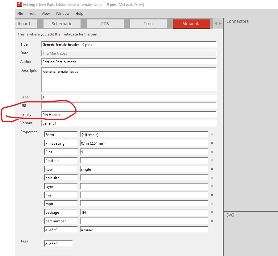
You need to modify the schematic svg with a svg editor such as Inkscape then load the modified svg in to Fritzing parts editor using the File->Load image for view option when in the schematic view then save the resulting part. You are best off to change the family name from Pin Header in the metadata tab to something that describes you new part as well.
Peter
via google translate
Sie müssen das SVG des Schaltplans mit einem SVG-Editor wie Inkscape ändern und dann das geänderte SVG in den Fritzing-Teileeditor laden. Verwenden Sie dazu die Option Datei->Bild zur Ansicht laden in der Schaltplanansicht und speichern Sie dann das resultierende Teil. Am besten ändern Sie den Familiennamen von Pin Header in der Registerkarte Metadaten in etwas, das auch Ihr neues Teil beschreibt.
Peter
all right - thank you ![]()
I thought, it would be displayed, if I change the names in the editor.
But since it is showing them as a tool tip, that’s also fine for now.
Btw: would be great, if renaming the pins would lead the designer to show the names, instead of what’s given in the graphic