Hi,
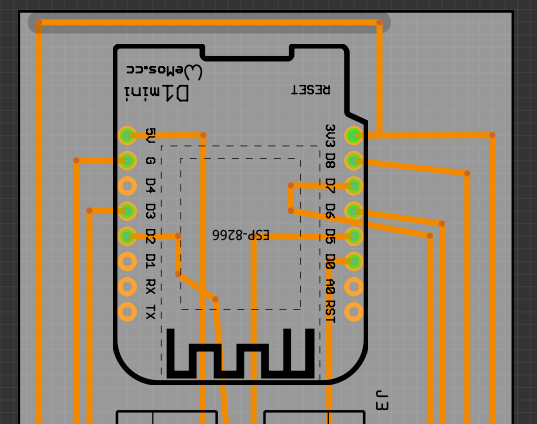
I’m just getting started with Fritzing and I’m using a WeMos D1 Mini1 in a circuit, but when I come to export the Gerber file, the pin holes are just in a straight line.
Could someone give me some pointers to what to do?
Many thanks
Dave
Hi,
I’m just getting started with Fritzing and I’m using a WeMos D1 Mini1 in a circuit, but when I come to export the Gerber file, the pin holes are just in a straight line.
Could someone give me some pointers to what to do?
Many thanks
Dave
You would need to provide more information. There doesn’t look to be anything wrong (except the holes are somewhat too small) in the gerbers from the Wemos D1 mini in core parts.
uploading a sketch (the .fzz file) which shows the problem is usually a better bet (upload is 7th icon from the left in the reply menu.)
Peter
P.S.
This is what is in Fritzing (please no comments on the acutal layout, its juts me testing and gettingused to Fritzing).

As @vanepp said, we need your actual “testing” sketch. The .fzz file. To be able to try to figure out what could be happening. Screen shots like this are enough to complain about the layout and routing used, but that is not the point here.
With a quick look at the 2 images, the traces, except for the outer one on the left, appear to line up, but not the holes. Those can be on different ‘layers’ of the gerber. What did you use to view the gerber output? I use gerbv, which has flags to turn different sections on and off. Which layers are in your view? With the .fzz file, we can create the gerber from the sketch, and see what happens.
Hi,
I wasn’t ‘complaining’ I was just seeking some help as a newby from some ‘experts’.
I’ve attached the .fzz fie as requested. I’ve just simpliifed it to focus on my quesiton.
Thanks
Dave
Test V1.fzz (42.2 KB)
Which answers the question (and is why I asked for the .fzz file!) The part you used is wrong (I’m too lazy to figure out why but it is creative to display correctly in Fritzing but break gerber post processing, probably transforms in the pcb svg!)
the gerbv output of your sketch which is indeed wrong.
Which came from a part loaded from points unknown rather than core parts because the part is in the temp parts bin of the sketch.
The D1 mini in core parts loaded in to your sketch (note the pins on the core part are probably too small beiging 0.036in rather than 0.038 as headers should be!) so if you intend to make boards a corrected part is in order. This produces this gerbv output
which matches the one I posted this morning.
Peter
Sorry, the sense of that came out backwards. What I meant was that screenshots like previously posted were enough for “us” to use to complain about layout and routing problems in your sketch. Not that you were complaining. But they were not enough for us to assess the cause of the problem that you were having. Once you posted the sketch file, Peter was able to quickly locate the cause.
Thank you both.
I think I can now sort it now, and I’ll be careful where I get parts from, this one was from a search on the Web. Not sure why I didn’t see the part in the library in the first place.
Thank
Dave