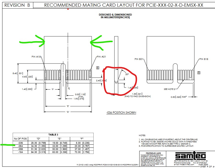
It is unclear to me what you need. The pdf is a connector intended to take a board. I assume your pc already has this connector and you are looking to make a board with a gold plated edge connector (rather than a Fritzing part for the connector?) If so the footprint for the connector isn’t likely useful, we would need the specifications for the fingers on the board (which are likely to be slightly different than the connector footprint. As well we would need to know where the fingers need to be in relation to the edge of the pcb. This site
has part of the layout of the pcb side of this (the width of the fingers is not specified and will need to be found from somewhere.) There are a few issues though. The slant on the bottom of the edge connector can’t be specified in Fritzing (the red circle), the number and pitch of the pins needs to be found somewhere as well.
Peter